
Vincent
Technical Sections: -Serial
Numbers/Production- Photo Gallery of
Models - Brakes
- Engine
Overhaul - Vincent
Engines - Wheels/Fenders
- Instruments -
Transmission -
Clutch - Magneto - Tank/Seat - Suspension
- Tools - Norvin -
Electrics-
Carburetors - Misc - Links -Vincent
Parts/Services Suppliers - Polishing/Cleaning
- Shipping Vincents-Electric
Starter - Paint/Transfers
Vincent Motorcycle Engines -
Technical Information
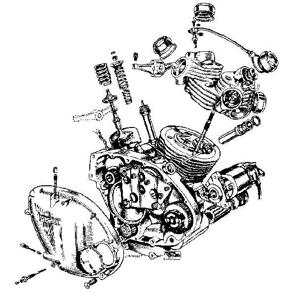

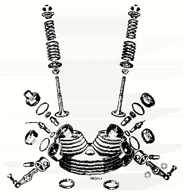
 (each can be enlarged)
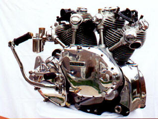 Andy Hopkin's Die Cast Rapide
Engine
Andy Hopkin's Die Cast Rapide
Engine
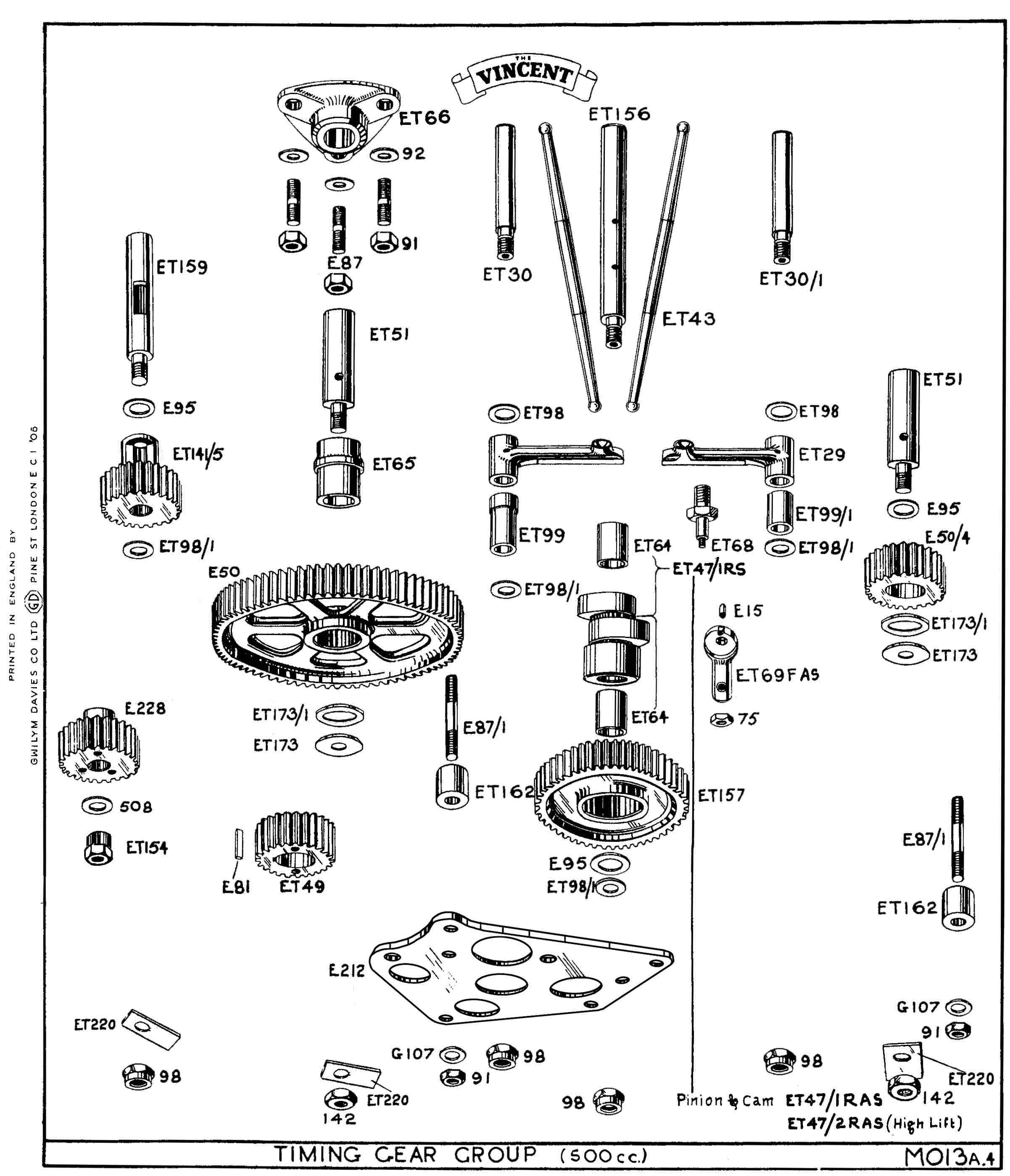 Comet Timing Gear Group. Revised 10/7/07
incorporating your comments. (Gwilym
Davies) Higher
resolution (revised) copy for your parts manual.
Comet Timing Gear Group. Revised 10/7/07
incorporating your comments. (Gwilym
Davies) Higher
resolution (revised) copy for your parts manual.
I hesitate to Constantly remind you... but
many of the following "practices" are highly
controversial... Proceed at Your Own Risk.
Engine Condition : by
Max Lambky 12/5/2011 At one time or another
most Vincent owners find it necessary to assess the condition of
their motorcycles, the engine being the primary part of the
inspection. The reasons for engine inspection are many. If the
inspection is made prior to the purchase, it could be a major issue
as to the final agreed upon purchase price. Another reason would be
to ascertain the degree of overhaul required to bring the engine
back to standard, and in the case of a restoration, to ascertain the
engine's condition, as it would be a variable in the cost of a total
restoration.
A pretty good assessment as to engine condition can be obtained
without a complete tear down and the use of a micrometer. Using your
five senses can result in a fairly accurate condition appraisal. If
the engine is a running unit, a lot can be deduced by simply
listening to the sounds omitted when running. Static sound tests and
riding sound tests are easy enough to initiate. Crankshaft big ends
and piston slap can usually be detected by a discerning ear during
hard acceleration and deceleration of engine parts. Bluish smoke
from the exhaust pipe during hard acceleration is most likely caused
by worn rings or excessively worn valve guides, or it may be
something as simple as missing overhead oiling wire restrictors.
Transmission parts and their wear can also sometimes be determined
by hard acceleration and deceleration in each gear. A whining noise,
jumping out of gear, or poor shifting characteristics, are all
symptoms of wear in the condition of the transmission. The engine
running in a static mode, can easily be checked by using a common
shop tool, the screwdriver. Place the working end of the screwdriver
on various locations of the motor, by holding the screwdriver to
your ear you can easily detect metallic noise. Engine parts that
have worn and excessive clearance will become apparent. Head,
cylinder muff, timing cover, primary cover, and engine cases should
be checked. Better yet than the screwdriver, a physician's
stethoscope would be a good choice.
A thorough visual inspection of engine and parts should be conducted
as well. Married parts, such as crankcase to crankcase, primary
cover to crankcase, timing cover to crankcase, should be checked for
oil leakage. Excessive leakage can sometimes be caused by warped or
poor mating surfaces. A visual inspection of the oil filter and the
drained oil, of both engine and transmission, are very important.
Metallic particles can tell you a lot as to engine condition. The
oil filter after a period of use, will always have some metallic
particles, this is usually of little concern. Cam timing gears and
other moving parts, are continually giving up minute metallic
particles in their wear. With the exhaust pipes removed, the exhaust
ports and their carbon deposits can also give you an indication as
to engine condition, also while the exhaust pipes are removed, check
the condition of the female threads of the cylinder heads. An oil
saturated carbon deposit on the port is an indication of leaking
valve guides or worn piston rings. Don't limit your visual
inspection to mechanical only. A thorough cosmetic inspection is
useful as well, in determining restoration expense. Engine finish on
Shadows and covers on D's, as well as broken fins, can add to the
restoration cost more than what one would think. Rounded hex head
nuts and bolts can also be expensive.
Feel and touch is also used to determine the condition of some
engine parts. One common check is performed by removing the rocker
arm caps, turning the engine over to where the cam of the rocker to
be checked is on it's heel. Grip the rocker in the area of the push
rod adjusting screw with a pair of pliers. Try moving the rocker
athortship of the bike. If movement is detected it's more than
likely that the rocker bushing bore in the head, and the bushing
itself, has given up it's interference fit, and is loose in it's
bore. This isn't good, but is pretty common in engines that have
several miles on them. Another feel check is one that determines the
amount of wear of the cam timing gears, idler gears, breather gear,
and magneto drive gear. This is done by checking for excessive back
lash. Remove rocker covers and back off all rocker adjusting screws.
Remove cam cover inspection plate. Rotate the fiber or nylon magneto
drive gear clockwise then counter clockwise. Too much rotation
indicates one, or more, or all, gear meshing teeth being excessively
worn. Repair can be as simple as replacing crankshaft half time
pinion to oversize. Often early aluminum or brass gears will require
replacement. The same goes for the fiber mag drive gear. All of
these gears are prone to wear.
The magneto automatic advance is checked as to it's condition in the
following manner:
With the magneto point cover removed, turn the magneto, expanding
the advance fly weights to their maximum. The springs to the fly
weights should be adequate in strength to return the magneto to it's
original position without a sluggish movement. If you get a quick
return, this will give you a pretty good indication as to the
condition of the weight's pivot points and it's mechanism, plus
magneto bearing condition and crush fit. Magneto spark should be
checked as well. Remove spark plugs. Take an old set of sparkplugs
that are functional and of the same heat range and kind, open up the
ground electrode to approximately 3/16" near the same as possible.
Tape over gapped sparkplugs hex nut to ground with duct tape. With
the engine out of gear, kick it over. Both sparkplugs on the twin
should show a blue to a blue-white spark at the gap. A yellowish, or
no spark, indicates that a rework of the magneto will be necessary.
A routine and most common practice in determining engine condition
is to perform a compression test, or leak down of the cylinders to
determine the ring seal and the valve and valve seat conditions. To
do either of these tests with confidence you must first understand
that compression ratio differs from compression pressure. For
example on a twin, if you increased the compression ratio from a 7
to 1 piston to an 8 to 1 piston, there would be no difference caused
by the change when performing a leak down. The leak down method is
the best of the two as it gives you the condition of the sealing
capability of the valve and the sealing capability of the ring. The
problem with determining engine condition with the use of a
compression gauge is that there is an 'unknown'. The unknown being
the cam timing, only in the case of the twin, from cylinder to
cylinder. Compression of the cylinder during tests starts at the
timing of the closure of the intake valve. Cam timing, such as it is
on most Vincent twins, leads to false readings. A reading of say,
155 lbs. pressure on one of the cylinders, and 160 lbs. on another
cylinder doesn't necessarily mean the latter is the better of the
two cylinders in their sealing ability. The Vincent owner who is
dealing with an unfamiliar engine is pretty much left with the leak
down method as his only recourse to achieve a true condition check
of the cylinders. Compression checks are made valid only when valve
timing, cam to cam, is proven to be 'spot on' by proper degreeing of
the cams.
It's a good idea for the new owner of a Vincent who isn't familiar
with the Beast, to employ a person of proven capability who's been
around Vincents for awhile to test ride and give his input on the
condition of the bike's engine as well.
Discussion
of Engine Balancing: When I was, I think, 14
years old, I bought a JD Harley Davidson motor from my motorcycle
mentor Burt McNew. Spent 10 dollars for the froze up JD, but it did
come with a manual. Strangely enough I still remember the pages that
had to do with balancing the JD's crankshaft. It explained two
parallel bars made level with a machinists level. It went on to say
with the crankshaft assembled without the rod assemblies make a bob
weight that can be affixed to the big end crank pin. The weight of
the bob weight should be equal to the weight of all the rods, roller
bearings, wrist pins, sir clips, rings, and one piston. Placed the
trued crankshaft on the parallel bars, drill holes as necessary in
the fly-wheels to achieve near static stability in any position of
the rotated crankshaft.I would guess as the pistons were quite heavy
that you would be working with a possible 60% balance factor.
Balancing of engines is pretty much a black art. Percent factors
of balance are only used in V-twin engines and parallel twins
where the crankshaft is not a hundred degree crankshaft. These
are the only engines that require a bob weight to balance the
crankshafts. Opposed cylinder engines, multi-cylinder V engines,
and inline engines with 2 or more cylinders all do not require a
bob weight to be manufactured and used. The crankshafts are so
designed that counterweights are equal.
There are 2 forces in balancing an engine that are corrected.
The first being the kinetic energy when spun, which is a direct
up and down, side to side straight force. The next is the
dynamic balance of the crankshaft, which is the movement forces
at the ends of the crankshaft. For practical purposes, a Harley
Davidson V-twin with the split-rod has its rod and piston mass
on a straight plane, which drastically reduces the tendency of
dynamic imbalance. In other words, it's a waste of time to pay a
lot of attention to blueprinting pistons or rods. e.g. making
the weigh the same. Do to the fact of the mass on a single
plane. Now, the Vincent can benefit slightly by blueprinting the
rods and pistons, e.g. making them weigh the same as the rods
are side by side and the weights are not on a single plane in
relation to the linear length of the crankshaft. Equal balance
of the pistons and rods on separate planes alleviates some of
the dynamic balance factor.
You wouldn't think that a flywheel, being balanced, would have
any dynamic balance input. It's pretty unbelievable, but they
do. A flywheel on an automobile, one half inch thick requires
dynamic balance often by drilling on both sides of the flywheel.
Both sides can correct the dynamic balance, but cannot correct
the kinetic balance. The kinetic balance can be corrected by
drilling on one side, but it's best to drill on both sides an
equal amount.
A dynamic balancing machine has adjustable spring pensioners to
counteract large masses to be balanced. Both knife rollers and
flat ball bearing rollers are used depending on the length of
the part to be balanced. For instance, a straight eight Buick
crankshaft, remember, requiring no bob weights, would utilize
ball bearing rollers on it's end main bearings. This would give
the most sensitivity to the machine as to it's dynamic balance.
Both kinetic and dynamic balance factors are corrected usually
simultaneously. V6 engines are the most cantankerous of all to
balance. Don't ask me why, it's too confusing for this wrench.
Now that I probably have everyone confused, I know I am. I'm
going to retire. Max Lambky
10/24/2011
Blueprinting a Vincent Connecting Rod:
Properly blueprinting a pair of Vincent connecting rods is easier
said than done, and takes more time than the average engine builder
would care to invest.
If you're privy to a rod stash, meaning more than two, the first
step is to select near likeness in their shape. Before you start to
blueprint the rods, save yourself a lot of time and grief by
magnafluxing to determine whether they're worthy of a blueprint.
Forgings varied, not due to forging procedures using the same
forming die. Variations were caused by various forming dies. I
believe as many as four die manufactures were utilized in the
manufacture of dies used by the Vincent Works. If you don't have a
stash of rods you have to make do with what you have. The initial
steps in blueprinting the rod is it's disassembly. Of course I'm
referring to used rods, not new rods. Push the big end bearing races
from the big end rod bore, and push the wrist pin bushings from
their bore. Clean the two rods thoroughly, especially the big end
and the little end bores. Discard the bushings and the big end outer
races. In a proper blueprint these items are made new. With a bore
gauge, check the roundness of the big end bearing bore of the rod as
well as the bushing end, or little end. Check the diameters of the
two bores as well. These dimensions are important for proper crush
of the new big end bearing race. The little end bushing bore is not
so important as oversize bushings, can readily be made, and aren't
that expensive. If the big ends are found out of round, it's best to
discard the rod and find yourself one that's round. Some fellows
hone the rod round, hard chrome the race, and regrind to achieve
proper interference fit. I'd only recommend this for engines that
are to be utilized in street use, not for racing. The desired
interference fit between the outer big end race and the big end of
the rod is .0015 any more crush than this will cause egg shaping of
the bearing. The cylindrical bore of the rod isn't equal in
strength. The portion where the rod I beam attaches to the big end
bearing boss will not distort. Approximately 210o of the big end
bore is subject to distortion due to lesser strength. Bushing
interference fit of the little end should be .001. This is enough
interference fit to prevent any turning of the bushing in it's bore,
even if it were to be subjected to racing rpms. Any less than .001
interference fit can cause the bushing to turn in it's bore, causing
oil starvation to the wrist pin due to misaligned oil holes bushing
to rod.
Before installing the big end race and the small end bushing, the
rod must be checked for straightness, both X and Y axis. For this to
be done accurately it's best to take the rods to an automotive
engine building facility that would have a rod aligning tool. If the
rods are the same length, i.e., the exact center of the big end bore
and the small end bore, another method is sometimes used. Two pins
approximately six inches long, one being turned on the lathe to
achieve a slide fit in the big end bore, the other being a slide fit
in the little end bore, can do the job quite nicely. Simply achieve
a slide fit through both rods with the two sized pins, where there
is no hint of interference or binding. If you can do this, the rod
is straight, and the X and Y are accurate.
Next, the rods should be checked for equal length. If the two small
end bores have the same diameter, and the big end bores are the same
diameter, you can measure the rod's length with the use of a
caliper. If the rod's measure the same length, go to the next step.
Rods will vary in length only a max of, say, .005. If you take the
longer of the rods and use the six inch steel pin used for checking
alignment, placing it in a press, holding the pin with V blocks, and
use an old piston, with wrist pin holes bored to align pin
diameters, you can press the rod, using about seven tons pressure,
to reduce it's length to match the other rod. No heat required. Work
up on steps, one ton, two ton, three ton, checking length of rod
between each press.
With all of this satisfied, the two rods now can be made equal in
weight. If the two rods are within 20 grams of each other, remove 10
grams from the heaviest of the two in the area of the outboard sides
of the I beam. Next, place the big end on a gram scale as near
center to the scale plate as possible. Using a hangman's tree,
suspend the little end with a string. Weigh the big end, do the same
with rod number two. Remove weight as necessary from the heaviest of
the two in the area of either side of the strong back web. Retain as
much of the strong back web as possible. This is the main strength
feature of the Vincent connecting rod, which contributes to nearly
90% of the rigidity, retaining roundness at high rpm.
Reverse the process and weigh the little end of the connecting rods.
Determine the heaviest, and remove material over a reasonable area
from the convex portion of the I beam, 1" below the wrist pin boss
of the rod. Remove equal amounts from both sides to obtain equal
weight. What you've accomplished by approaching weight removal in
this manner is equalization of the reciprocating weights and the
rotating weights of the two con rods. A light polish to remove any
sanding scores over all areas of both rods is the next step.
For racing engines drill an additional oil hole in the center of the
convex and at the radius of the little end boss 1/16" in diameter.
With a quarter inch counter sink, champher the outer end of the
drilled hole.
Mask off the inner bores of both the big end bore and the little end
bore of both rods. Find a source that has the ability to shot peen.
Shot peen both rods to a matt finish over all surfaces. Now you're
ready to insert the new outer race of the big end bearing into the
now blueprinted rod. Ensure that the rod in the bearing has a .0015
interference fit, as mentioned before. Bearing, sleeve, lube of your
choice, should be used to aid in a slight smooth friction push with
a press, negating any chance of gaulding. Use same procedure on
little end bushings. If the little end bushings have not been
predrilled, drill bushings slightly undersized of rod oil holes.
This requires the use of numbered bits. Reduce the hole to be
drilled by three numbers. After drilling, deburr the inner portion
of the drilled holes. When drilling, adjust drill stop so as not to
damage the adjacent wall of the bushing.
Now you can fit the wrist pin to it's bushing bore and the big end
cage roller clearance. The little end requires reaming to obtain a
slide fit. This fit is the same whether used for racing or high
speed touring. Fitting the big end roller clearance is best done by
a professional with the proper honing equipment. Clearance for
street use is between .001 and .0015. For racing .002 to .0025. Some
would say this is too much clearance, however, I've found that the
greater clearance reduces roller skating when a blower is used, or
with high loads of nitro methane.
A blue printed rod helps a tad to reduce vibration, increases the
strength of a standard rod by maybe 15%. The blueprinting procedure,
when done properly, pretty much parallels the Vibrac rod. Neither of
which is up to a Corrello rod's specification, or their ability to
withstand the abuse of racing as well as the Corrello. For racing,
one would use a standard rod or a Vibrac rod only to retain
originality. The choice is yours. Max Lambky
10/9/2011
Replacing the Upper Pushrod Seal:
You'll have a 75% chance of sealing the leak without pulling the
head by replacing the seal between the pushrod tube flange and the
cylinder head machined flat. Here are a few pointers to make the job
go smoothly. 1. Before loosening the gland nut, ensure there is at
least one thread visible. You are checking the crushed two fiber
washer thicknesses. As you are only replacing one gasket instead of
two, you must determine that there are enough threads on the gland
nut to provide adequate crush on the new seal before the gland nut
runs out of threads for tightening. 2. Next remove the rocker cover.
Turn the engine over to where the cam follower is on the cam heel.
Remove the rocker adjuster, then the push rod. Loosen the gland nut
totally out of it's threads. You can now slide the push tube cover
in it's crankcase bore to the point to where it stops against the
cam lifter. This will give you the most distance between the push
tube and the cylinder head for the upper gasket removal. 3. You can
now with a 90o scribe, remove the upper seal. The one's I have have
a handle on them for grip. If you don't have one of these types of
scribes, you can take a normal type scribe, bend the end (usually
takes heat) to where you have a 90o, 1" long sharp end. Then clamp a
small pair of vise grips onto the opposite end of the scribe. This
will give you a tool with which you can remove a sometimes
cantankerous upper seal in it's totality. 4. When you reassemble the
parts, separate the the gland nut from the seal. Lightly coat the
seal without disturbing it with permatex #2, the non hardening
stuff. The reason for not disturbing the seal is that often they
have hardened and become quite brittle. Coat the threads of the
gland as well. 5. I've heard that some have renewed both seals by
soaking the seal between the packing gland nut and the lower portion
of the tube flange in hot water. Then they make a herring bone cut,
splitting the seal so it can be installed. I've never tried this,
but it could possibly work. Max Lambly 5/1/2011
Big End
Flush:
It's not uncommon to hear of a big end failure when a machine is
started up and run after having been sitting for years or even
decades. Sometimes - maybe most of the time - it doesn't happen
right away; the mechanism perhaps being that the tiny oil path
"down there" through the flywheels and rollers gets heated up
thanks to gummed up oil and goo that has semi-solidified over
time. Even with modern detergent oil, the stuff is not
pushed out, so only minimal oil feed occurs, if at all. Even if
the damage at first is minute, once things start going bad it
snowballs until the roller and races get all angry and
eventually grind to a halt. So, a happy startup suddenly ends
after a few hundred miles or
maybe even a thousand. We might hear of more of this happening
these days if all new Vincent owners of barn finds went riding.
But, as we often see, a new owner gets the bike running, feels
great about it, then mostly lets it sit, only
occasionally going for a short ride, never really knowing they
are sitting on a time bomb.
With the oil drained, the quill removed and the sump drain plug
out and the bike on the rear stand, shoot some solvent into the
quill. With the bike in 4th gear, rotate the engine (spark plugs
out). Squirt, squirt, squirt, at different
positions of flywheel movement. After lots of squirting give it
a few (light) bursts of air for encouragement. Squirt some
more and let it sit overnight, allowing the solvent
sequestered there do its thing. At this stage you might
want to use WD40 or something similar as it will not dry up as
easily as the meaner stuff. Next day squirt some more solvent
and do a final air burst with the bike on its left side stand.
When you are confident there is flow, get all
the solvent out of the sump and then with some very lightweight
oil get some oil flow through there. When you are confident that
is done, introduce engine oil. Bev Bowen 4/18/2011
Starting an old Vincent engine:
There is no substitute for using bike often... starting and warming
through for a longish run, change oil and filter at regular mileage,
thin in winter thicker in summer, but they do run okay on a 30 wt
oil, the big ends get clogged up with crap in that oil groove
and nothing will move it only to take apart and clean it... gets so
hard no amount of WD40 or gunpowder will shift the
stuff. In my mind an older motor should not be started
without dismantling and given a good thorough cleaning. Mike
White 4/18/2011
When you switch from a non detergent
oil (ND) to a detergent oil, built up sludge becomes
loosened and goes back into suspension in the oil due to detergent
action on it. In a high enough concentration in the oil it is very
detrimental to wear especially in high pressure plain
bearings. All engine oils will build up sludge in suspension
over time both from combustion product contamination as well as
breakdown of the oil itself (especially in the case of plain
bearings). Older engines using non detergent oil relied on a
settling period, either in the sump (autos) or the oil tank
(motorcycles) to allow the suspended matter in the oil to settle out
as a sludge. These engines use primitive oil filtration, usually a
only fine metal gauze to trap out large foreign particles. In
later engines where detergent oil is used the contamination products
are deliberately maintained in suspension by the detergent but are
continuously removed by a much more sophisticated and finer high
surface area filter in the form of a paper cartridge or element.
This is one reason why its necessary to regularly change oil filters
in modern engines. The post war Vincent is an interesting
hybrid in a way. It does have a relatively sophisticated filter
system for it's time compared to say a fifties Triumph or BSA in
that it has a fine wool element incorporated in addition to gauze
which, whilst not as efficient as a modern filter, does trap some
suspended matter. It also has a long residence oil tank for sludge
deposit. However if you replace the original element with the
newer much finer paper cartridge element that's available it becomes
in essence no different to a modern engine. You have the best of
both worlds, a highly efficient filter and a large sludge settling
tank. You can happily operate it with either type of oil. Even if
you you inadvertently add detergent oil to what has been an ND
engine to date any sludge loosened up should be effectively caught
by the paper cartridge. In an older looser engine my thought
would be to replace the element fairly regularly either way as it's
not particularly large compared to that of say a late Norton or
Triumph (using essentially an auto filter) and I would assume it to
have a fairly modest capacity. Tim Holcroft
4/18/2011
Oiling Your Vin: by
Max Lambky 3/30/11
There are four separate and distinct methods to which moving parts
are subjected in regard to their lubrication. They are drip,
pressure, splash, and mist. The drip happens when the oil
return pump sporadically returns oil to the oil tank through the oil
return line. The line is open to the oil tank, thereby
negating any pressure development from a metering orifice, or closed
end. There is no pressure in the return line, only sporadic
volume head pressure, which is quite minimal, as the only volume
head pressure is created by the amount of oil that is in the return
line, which is the mere amount of oil contained in a quarter inch
inside diameter line, sixteen inches in length. The amount of
oil that's allowed to drip through the overhead oiling system at
140o F. temperature, is only approximately 12 to 16 drips per minute
with the restricting wire removed. The restricting wire
reduces the drip flow to 8 to 12 drips per minute. There's no
difference in the amount of drips from 50 wt. oil to 20/50 wt. oil,
when the oils reach 140o F.. This is the only portion of the
lubricating system on a Vincent that's not increased in proportion
to engine rpm. The engine at idle receives the same amount of
oil through the overhead rocker oiling orifices, as it does at 6500
rpm top revs.
Other parts of the engine oiling system controlled by drip orifices
are the cam timing idler gear spindle, and the oil pump worm
gear. Here again, these are zero pressure lubricated. Don't
confuse the parts that are oiled by splash and mist, with the parts
being oiled by drip. Drip can only be created when the mist
and splash finds it's way to the inner surfaces of the crankcase's
primary case, transmission case, and push rods. When the
wetted surfaces are such that the amount of oil is saturated to the
extent that gravity takes over and causes the oil to run, much like
when shooting paint to excess, drip is created. Some surfaces
extend without interruption to the sump, and no drip
occurs.
Splash lubrication is accomplished when a moving part passes through
a reservoir of oil, or a solid stream of oil is pressure fed to a
moving part. The transmission and primary case, both
containing an oil reservoir and moving parts, are examples of splash
lubrication. No pressure involved. Machined canal
passages are utilized to facilitate the lubrication of the bushings
and shafting in the Vincent's use of the splash system.
Bushing canals are sometimes enhanced in their lubrication ability
by spiral machining much better than with a straight broached oil
canal.
Three other engine parts are being lubricated by splash, the cam
timing gears teeth, the non thrust side of the cylinder walls, and
the little end of the con rod.
Moving parts that are oiled by pressure are the thrust sides of the
pistons, the crankshaft's big end, and the two camshaft spindles.
(or should I say the cam bushings and cam lobes?) The oil
pressure to lubricate these parts is created by the pressure side of
the oil pump. The pump being a plunger, and the cylinder feed
ports' opening and closing by the piston's passing over them, causes
an inconsistant sporadic pressure variance. As the pressure
oiling system feeds a manifold which contains five outlets, the
amount of oil to each outlet isn't equal in volume. The oil to
the cam bushings is less than the oil to the thrust side of the
pistons. The oil to the thrust side of the pistons, in volume,
is less than the big end of the crankshaft, due to the fact that the
crankshaft acts as a centrifuge, increasing pressure and volume at
the big end oil holes. The oil volume is actually increased by
a suction action on the oil manifold, caused by the centrifuge of
the crankshaft. As crankshaft rpm increases, the volume of oil
to the crankshaft increases as well. The supply to the
manifold is increased with engine rpm. The volume of oil to
the five manifold outlets isn't proportional and constant through
the rpm range.
All main bearings except one are oiled by drip or mist. All
transmission gears and bushings are oiled by splash. All
clutch bushings, primary chain, sprockets, and outer ball bearing
main, are oiled by splash.
The windage of the moving parts, mainly the crankshaft and the cam
gears, cause oil mist. Little, if any, mist is caused by
rocker arm movement, or cam lifter movement. The mist
permeates throughout the entire inside of the crankcases, cylinder
head, and oil cavities. This mist covers all parts, and some
are actually lubricated from the mist. The timed breather is
mist lubricated. This is why the timed breather requires more
clearance than would normally be necessary, if it were pressure
lubricated. The cam lobes receive very little additional
lubrication from the inner sidewalls of the push rod tube.
This oil is no more than a drip caused by gravity, it leaving the
end of the tube, and falling on the cam lobe, which is spinning,
actually repels the drip. Try to oil a fan blade in motion,
and you'll see the problem with trying to lubricate by drip.
The additional oiling to the cam lobes and lifters, the first being
the pressure lube of the parts, and the second being due to the
phenomena of wicking. The oil mist adheres to the push rod,
and when saturated to a point of a gravity induced run, the oil
wicks itself to the end of the cam lifter. The oil wicks
through the hole in the end of the lifter, and is then guided by a
groove on the lifter work side, and wicks it's way to the cam, where
it lubricates the two moving parts. The pivots on the cam
followers are lubricated by mist. All rocker pressure points
are lubricated primarily by mist. The rocker arm push rod end
is lubricated by mist, the lower push rod end is lubricated by
gravity wicking.
The grooves in the crankshaft's feed quill assist in keeping the oil
going the right direction. This action is employed as well
with the groove spacer between the ball and roller main bearings on
the drive side. Oil mist increases as engine parts wear.
Older engines with more hours on them will mist more than a fresh
engine. Usually oil pressure reduces as an engine wears.
Splash increases when viscosity decreases. Low viscosity oil
produces more mist. The oil pump and it's cam drive pin are
lubricated by pressure.
Oil Sumping:
Oil by gravity is fed to the oil pump first through a filter screen,
then through a check valve, from there through a line partially
rubber and partially tubing. A banjo bolt connects the oil
supply line to the engine. Oil then flows through a short port
in the engine to the oil pump intake port. The oil pump
consists of a small engine supply pump on one end, and a larger
engine return pump on the other end.
How does oil get to the sump from the supply pump port? Think
of the supply pump in it's brass bore to the likeness of a leaking
petcock valve, i.e., leaking between the clearance between the pump
and it's housing. From there, there are two paths to the
sump. One being between the pump and housing clearance to the
opening relief of the oil pump housing, required for worm gear
engagement to pump gear teeth. Next is the oil passage from
the pump to the oil filter cavity, then to the timing cover oil
passages through the timing cover banjo bolt. Oil is then
transferred by gravity through the built in cast passageways in the
timing cover, to the two cam spindles, which then can find it's way
through the clearance between cam bushings and cam spindles.
Some oil is returned to the sump through drilled oil passages in the
cam lobes, and some oil enters the sump through both ends of the
cam. Other oil returns to the sump from the oil passage in the
timing cover to the crankshaft quill ports to the crankshaft main
shaft center drilled oil port. Oil then, depending on
crankshaft position, either returns oil to the sump past the
labyrinth of the oil quill to the end of the crankshaft, where it
enters the timing chest and then to the sump. If the
crankshaft's big end is at it's bottom, nearest the bottom of the
crankcase, oil flows through the main shaft oil passage, then to the
crankshaft's drilled oil passage, then to the two big end's oil
passages, then through the bearing cages, and into the sump, which
is the path of least resistance over the quill's resistance.
Actually, the most common return passage is from the oil intake port
on the pump past the outer circumference of the brass housing
clearance to engine bore clearance. This is why quite often an
oil pump replacement with tighter clearances doesn't solve
sumping. Max Lambky 11-4-10
Cam Timing Restoration: by Max
Lambky
More often than not, when a total
restoration is undertaken, there will be a mismatch of
parts. Usually the timing chest requires much
attention. With old iron it's not uncommon to find that
cams have been replaced. This is sometimes due to
rounding off the lobes to an unusable state, but is more
commonly due to after market performance cams, and due to the
fact that factory racing cams were installed to enhance the
bike's performance. When racing cams were installed properly,
the performance was enhanced, but often the cams were
improperly installed, causing an actual decrease in
performance. The reason usually was due to improper
positioning of the cam gear to the camshaft. During
installation of the camshafts, where the camshaft and the gear
weren't properly aligned, and the builder relied on punch and
scribe timing marks on the two cam gears (the idler gear, and
the half time pinion gear) the proper cam timing suffered,
causing poor performance. To eliminate the possibility
of improper cam timing after restoration, the following
procedures are recommended.
First you have to attach a degree wheel to the
crankshaft. On an assembled engine, remove derby,
clutch, and primary cover. Clean exposed nut and
crankshaft with brake cleaner to remove oil. Wipe
clean. Apply adhesive backed Velcro to crankshaft
end. Apply adhesive backed Velcro to degree wheel.
Affix degree wheel to crankshaft, achieving a reasonable
degree of centering. Attach hand made pointer to any
primary cover bolt hole that's reasonably close to degree
wheel. Sharpen pointer to enhance readable accuracy,
i.e., pointer to degree wheel.
Remove the following items timing side. Four rocker
caps, two intake valve spring cover caps, four push rods and
adjusters, timing cover, cam spindle steady plate, half time
pinion nut, cams, (both front and rear on twins) idler gear,
timed breather gear on B's and C's, half time pinion
gear. Don't remove half time pinion gear key from
crankshaft.
Remove sparkplugs. Install handmade stop in rear
sparkplug hole. Stop is made by removing all porcelain
from a sparkplug, inserting 3/8" rounded rod, so as to provide
a protrusion of approximately 1 3/4" extending from the bottom
of the threaded steel portion of the sparkplug. Weld or
braise rounded rod to hold secure.
Turn the crankshaft in the direction of rotation until piston
hits special tool stop. Procede carefully, damage to
piston is possible. At the pointer, with a felt tip,
mark the degree wheel. Now turn the crankshaft in the
opposite crankshaft rotation. Do the same. Mark
the degree wheel at the pointer. Remove piston
stop. Mark the degree wheel half way between the two
pointer marks with a felt tip. Identify the mark as
TDC. Turn crankshaft and align TDC to pointer
point.
Next determine the manufacturer's recommendation for intake
valve opening. All cam grinders producing after market
cam grinds will provide this information. MKII Lightning
cams work best for a wide band power range, using the opening
figures of 50o before TDC at .010 off the seat. We'll be
using the procedure for proper cam timing, with the MKII cam
intake opening figures. Of course this would only apply
if you're timing MKII cams. Obviously you'd be using
figures supplied by cam manufacturers if their cams were being
used.
Next position the rear cylinder's piston 50o before TDC.
This is done by rotating the crankshaft 360o in direction of
rotation, stopping the crankshaft at TDC, pointer at TDC, then
turn crankshaft counter to crankshaft rotation by 50o.
With a felt tip, mark degree wheel R 50o BTDC. R
indicating rear cylinder.
Place a dial indicator on the intake valve stem's exposed
end. Remove the exhaust cam lifter on the rear.
With a screwdriver lift the intake lifter, and insert rear cam
on cam spindle. Install rear intake pushrod in rear
intake cam lifter. Insert valve adjuster. Adjust
lifter, taking valve lash from adjuster and valve lifter,
i.e., lifter is on heel of cam. Install cam idler
gear. Turn idler gear counter clockwise until dial
indicator reads .010 lift. The intake valve will be .010
off of it's seat. Hold idler gear in this
position. Now take half time pinion gear and find the
keyway of the pinion gear, which lines up simultaneously with
the mesh of the half time pinion tooth with the idler
teeth. Slide the half time pinion home. Relax
pressure on the idler gear. Check that the .010 opening
is retained on the intake valve. If not, redo. If
so, go on to the next step.
Remove the rear cylinder intake push rod. Mark the idler
gear mesh, cam to idler gear, and idler gear to half time
pinion gear with a felt tip. Rotate crankshaft in
direction of rotation 360o+50o. Move front cylinder
exhaust valve lifter, holding in place with a dab of
grease. Install front cam on cam spindle. Install
intake pushrod. Lift front intake cam lifter with
screwdriver. Insert cam in any position on idler gear,
as long as the heel of the cam is adjacent to the cam
lifter. Install pushrod adjuster. Adjust and
eliminate valve lash to zero clearance. Move dial
indicator to end of front cylinder intake valve head.
Adjust dial indicator to zero. Lift intake valve lifter
until indicator reads .010 lift. Remove front cam by
sliding on spindle until idler gear and cam gear release
mesh. Turn cam gear in direction of rotation until mesh
is achieved between idler and cam gear, and a slide fit is
achieved, lifting ramp cam lobe to intake cam lifter.
Relax pressure on intake lifter. If the dial indicator
still indicates .010, the cams are precision timed to each
other and to each piston position, both front and rear
cylinder. For this step to come about the first time is
wishful thinking. More than likely you'll have to push
the cam out of it's gear bore with a hydraulic press.
Refit cam to gear relation by rotating gear to cam
slightly. Note which way you should rotate the two parts
when going through the steps to achieve a slide fit that's
lobe to lifter, and cam gear to idler gear. In most
cases it takes more than one stab to achieve the .010 off the
seat, and a perfectly coinciding mesh with the idler gear and
the cam gear. This last step can't be over
emphasized. As this is the step that precisely times the
cam gears to each other and the piston position to intake
valve opening.
On the B's and C's, where a timed breather is employed,
proceed as follows. Turn the crankshaft counter
clockwise 50o. This will put the front cylinder at
TDC. Then rotate the crankshaft in crankshaft rotation
15o. Locate the port in the breather spindle.
Locate the port in the geared breather. Turn the
breather counter clockwise and time the opening of the
breather. The knife edge of the breather gear will
coincide with the leading edge of the breather spindle when
the breather gear to front cam gear is in mesh.
Now you've timed the cams and the breather without the use of
timing marks. If you've followed the above procedures,
your timing will be far more precise than 90% of the Vincents
on the road. Remove all existing timing marks with a
Dremal sander. You can now remark all of the meshed
gears that constitute the cam timing gear train, plus the
timed breather. Remember to mark the half time pinion
keyway as well. You can now reassemble the motorcycle
using the new timing marks with confidence that the cams are
properly timed.
If you're tuning for speed, the keyway in the half time pinion
is so designed as to allow a veneer timing of the pinion
gear. The rule of thumb is if you were to advance the
cam timing a tad, not more than 10o, you would increase bottom
end torque. If you were to retard the cam, again not
more than 10o, you would move the torque curve higher, closer
to top revs. Max Lambky 10-29-10
RIP TRAGLE'S TIMING CASE
REVIEW
by W.I. Tragle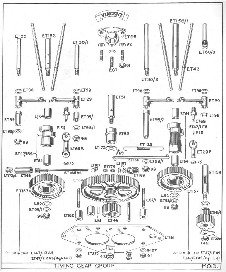
Object:
To remove all excessive clearances in the timing chest to include
pinion to gear clearance, side slop in cams, idler gear and
followers. To insure positive follower to cam relationship (in other
words the followers must run dead center on the cam lobes and stay
that way. ) Remember, if there's room for something to bang
around in, it will bang around.
Materials :
1, Good Cams--with bushes that fit the spindles .0005-.0015".
New bushes can be found at a bearing supply house and center honed
to size by any good machine shop.
2 . Good Spindles--No ridges at all--no wear. I recommend G.
Emmerich's spindles for reasons that will become obvious later.
3. A round Idler Gear (Chicago Steel) or check yours. Aluminum is
good too--but it must be no more than .002"out of round-- and .002"
is a bit much.
4. Good cam followers--I'm convinced there is no such animal. But
the followers must be re-ground true to the pivot hole. Also many
followers have oversized or out of round spindle holes--throw them
away !
5 , One Piece Idler Boss--¾ thousands--1½ thousands
clearance, clearance between idler pinion and idler boss.
6. A Good 1/2 Time pinion Gear--The 1/2 Time Pinion comes in
several over-under sizes ...you won't know which size you need until
you set up your cams & Idler Gear.
7, Three packages of PSW Brand Arbor Shims in 3/8", 1/2'' and
5/8" i.d.--Precision Steel Warehouse, Inc., 3500 N. Wolf Rd.,
Franklin Park, IL 60131. These are usually available at a good
machine shop supply house. Make sure you buy the shims without the
keyway notch. They come in packages of assorted thicknesses for
about $3.00 per package.
Procedures:
1, Start with the cams. Place cams on shafts with a washer under the
spindle nut to take the place of the steady plate. The thickness
of this washer is meaningless what you want to discover is the
side to side play of the camshaft with the E95 in place, You want to
reproduce its actual running condition. (Here comes the scary part
which I'm going to get flack about.) There are t w o ways to get
minimal side clearance. Shim
the cam at the rear with the 1/2'' arbor shims or move the spindle. If
the side clearance is tight you have to draw the spindle out
slightly which is done by putting large washers on the cam
then using the spindle nut as a puller works great. It's also a test
for loose spindles which can be fixed well with Loctite. The reason
I recommend George's camshaft spindles is because of the fact that
they are very tough. I don't like to shim the camshaft if there is
excessive side clearance I assemble the cam as above with the E95
thrust washer and a washer tightened down on the shoulder of the
spindle and I hit the spindle with a hammer! (A Harley- Davidson
type.) George Emrnerichts spindles are so damn strong that we have
done this without protecting the end of the spindle with no damage
but, with stock spindles, build up a pile of washers (3/8") until an
old nut threads on without exposing the end of the spindle--then hit
the nut. The object here is to take the brunt of the blow from the
threads to the shoulder of the spindle itself.
Now I'm going to hear how this method ruins the case-to-spindle
press fit and all that. If you're really worried heat the case
around the base of the spindle--but I don't recommend it because you
can overheat the spindle. Moving the spindle a few thousands in one
direction or the other will not hurt anything. Now that correct cam
clearance his been obtained it's time to assemble the followers.
With the cams loose on their shafts (you have to be able to take
them on/off the shafts) put one pair of followers on their spindles
as described in the Vincent books--do the above thing to the
follower spindles. put a temporary washer in place to act as the
steady plate and tighten the follower spindle nuts down. (Remember
that to remove and insert your rear intake follower your compression
release rod must be removed). Slip cam on its spindle and, if your
heads are off, look down through the push rod tube holes and see if
ox not your followers are running dead-center on your cam lobes. If
the heads are on, you have to use a flashlight and lots a neck
bending to see around the camshaft gear. If I can't look down
through the push-rod holes I judge the cam/-follower relationship by
lining up the edge of the follower with the edge of the cam lobe.
It's helpful here to have a pointed rod to poke in there and
actually feel for any over-lap one way or the other. The object here
is to either add to the thickness of your ET98s or subtract from
them to get your correct case-to-follower distance with perfect
cam/follower alignment. This is where you use your assortment of
3/8" arbor shims.
After you've established correct follower placement you must
reassemble all the spacers ET99, ET99/1, ET99/2, etc. with the
washer that acts as the steady plate--tighten the spindle nut and
check side play. Remember now that the follower is spaced to the
case and you mustn't change that
spacing. All spacing for side thrust must be done on the outside
(offside) of the followers. If after tightening the spindle nuts the
follower is jammed you must take material off your long spacer
(ET99,/1,/2) until the long spacer will turn with the nut tightened
but having no side play. You don't want the longer spacer to drag,
but you don't want side play either. If you do have side slop, you
use your 3/8" arbor shims wherever they will fit on the spindle
without fouling the camshaft gear wheel.
Your front exhaust follower is a special case due to its cute
location, You do same as above--the trick here is to "glue" your
arbor shims to each side of the depression in the case with
"assembly lube" or light grease, This holds the shims in place while
you carefully insert the follower between them and insert the ET30/3
spindle snug it down and check side slop--KEEP WORKING UNTIL YOU GET
IT RIGHT--NO SIDE PLAY WITH THE FOLLOWER DEAD CENTER ON THE CAM
LOBE.
Fitting Idler Gear:
With cams and followers in place check fit/side play of large idler
you want to shim this (if necessary) to run true with the cam gears.
Fit idler boss in place--run the 3ea ¼" nuts and washers down
snug--just so you can barely move the idler boss up, down and
around. (That's why the holes in the idler boss are oversize.) Slip
the idler gear into place without +, time pinion in place. Move the
idler pinion up until there is 0 (ZERO) backlash between it and the
cam gears. Tighten the three idler boss hold-down nuts. Check for
zero backlash by holding the idler tight and trying to rotate the
cam gears back/forth. If there is any back/forth play you must
loosen the idler boss and correct it. When this is done rotate the
idler gear. THERE SHOULD BE NO TIGHT SPOTS DURING 360 ROTATION. If
there is the idler is a bit out of round and you must re-adjust the
idler boss to allow for the high spot; Dig?
When the large idler is fitted to your satisfaction, slip it off the
shaft, Install the half time pinion on the main shaft, Re-install
the large idler. If you can't get it on, the 1/2 time pinion is too
big and you need a smaller size. If it goes on and there is play
between it and the half time pinion, it may be too small, you
need a bigger 1/2 time pinion. You want ZERO to .002" clearance
between the idler and the 1/2 time pinion. .002 backlash is almost
unnoticeable. It would be nice to have an assortment of over and
under size 1/2 time pinions at this point. Good Luck.
A good trick is to remove one large idler boss hold down nut at a
time (so you won't loose adjustment) and apply Loctite and re-fit
it. I don't believe in punch locking; it ruins parts and makes
taking things apart hard, Loctite works! Believe in it.
Now, with everything in its place, fit the steady plate after
you've lined up your timing marks of course. Use blue Loctite on
plain nuts here instead of punches and folding washers. Don't
Loctite the four oil-feed shaft nuts--they are self locking nylock
and won't 'unscrew anyway. Another problem you run into with punch
locked studs is the fact that many times the stud comes out of the
case instead of the nut corning off the stud. If this occurs, take
the stud out of the case, hold it in a vise or Vise grips on the
unthreaded portion and take the nut off. Dress the punch damage with
a file, make sure the nut will start on easily. Now put it back into
the case with Loctite "Stud & Bearing Mount" (part #2226).
..it's red. Use Loctite spray primer to clean the threads. This is
much stronger than the Loctite (blue) that you use on nuts. This way
the nut will always release leaving the stud in the case where it
oughta be, DON'T PUNCH LOCK, DAMN IT, I have never written
directions before so I may have over-looked something--my hand is
tired- [what about me, mate? (the typist and so It s my head. [ just
like Gumby of Monty Python, "My brain hurts!] But the general
idea is there. And nothing can replace care/patience, I suggest
everyone read Zen and the A r t of Motorcycle Maintenance, it's more
important than any Vincent manual--read it!
I always put transmission in high
gear, not low, when bumping with the rear wheel to set
valves, ignition timing etc.. Far less piston travel when
you bump the wheel, easier to bump, finer adjustments. The
engine turns over appx three times slower in high than low when
turned by the rear wheel, making tasks such as reading the
timing spoke, turning the engine against valve spring pressure,
etc. much easier. Paul Zell 8/9/10
Camshafts: I
have been told that Megacycle bought the Emmericj/Andrews cam
designs. I have those in my bike and I was told to split
the overlap at TDC at .050" lift, which is what Max, Tom, and
others have basically been saying. This means if intake
opening is at 0 deg and exhaust closing is at X deg, make the intake
opening at 0 + X/2 deg. Then you can retard that for
more peak power or advance it for more low down
torque. That is over-simplified, but you bike will run
fine at 0 + x/2
deg. Bruce Metcalf
7/28/10
Shifted Flywheels: If your feed quill shows
rubbing / wear on both ends - but on opposite sides is
indication that flywheels have shifted. For more
dramatic evidence of shifting obtain a
length of quality 1/4 inch dia. steel drill rod a foot
long or better and dead straight. Slide this up
into the right side quill passage untill it bottoms
out. Give it a light tap to seat it. With someone
rotating the motor via the kicker you kneel and observe the
end of that rod end on. If it spins with a decided oval
pattern to the movement that's a pretty good indication
that the flywheels have shifted. The nearer to no wobble the
better. Sid Biberman 7/28/10
Valve Timing: All you need is one dial indicator
to time the cams. Remove the half time pinion gear from the
crankshaft. With a degree wheel, place the rear cylinder 37o
before TDC. Remove all of the pushrods except the rear
intake. Place your dial indicator on the intake valve head
at the top. With your fingers, grab the idler gear and turn
until the intake is .050 open. Lock the idler and cam teeth
with a screwdriver in that position. Now you can find the
keyway slots that best time the cam in that position, by sliding
the halftime pinion gear on the crank. When this position is
found, the key should tap in or slide in rather freely. Now
rotate the crankshaft, using the attached degree wheel for
reference, 410o. This will put the front cylinder 37o before
TDC. Place the dial indicator on the front cylinder intake
valve stem head. Mark the degree wheel and the pointer so as
not to loose the 37o position. Back up the engine 50o.
Remove pushrod from rear intake valve, and install intake valve
pushrod on front cylinder. Adjust properly. Rotate
engine in direction of rotation to the previously marked timing
position. You should have a reading with the front cylinder
at 37o before TDC of .050 on the dial indicator. If you
don't have the .050, the front gear will have to be pushed off of
the front cam, and relocated, until you achieve the .050. Max
Lambky 7/9/11
Porting a standard head to it's
maximum requires 90o plate flange bolted to the head. The
plate flange should be 3/8" thick, and it's manifold mounting
flange studs should be 2 1/4" from center to center.
To accomplish the mod, remove the two studs in
the cylinder head. The threads are one quarter twenty.
Take two quarter twenty Allen head screws, one inch long, and take
the outside diameter of the Allen portion down .010.
Manufacture a flange from aluminum, using the dimensions
above. Manufacture the flange with counter sunk mounting
holes, so that the flange can be bolted to the cylinder head with
a thin paper gasket. You can now take the port to it's
maximum size, and achieve much better flow characteristics by
raising the port to it's maximum. You now have a wider
horizontal bolt pattern flange, compared to the perpendicular
narrower bolt pattern flange. Make yourself an aluminum
manifold, keeping the bend as high as possible. The manifold
should be a spigot mount, opened up, and blended to a 36mm
size. A 36mm Mikuni is my choice for
carburetion. Max Lambky 3/12/10
Valve
Timing: Timing marks may
not be correct as the wheels may have been pressed off the cams at
some time, checking timing by lift is better. Equal lift on
both inlet and exhaust at around four degrees before top dead
centre seems to be the ideal to aim for. There is no need to
remove the timing cover, just put a degree disc on as
normal. I checked mine for the overlap position and with Mk1
cams the the rear came out with equal lift at 7° and the front
5°. It might be possible in this instance to play around
with the timing pinion keyway to get one cylinder or the other
closer to 4° but as it runs fine and there is no spray from
the carbs it is OK for me. You may be able to remove the valve
caps and do a rough check by eye without dial gauges to find the
"rocking" position of the tappets. Eddie 5/11/10
Valve Timing: A foursome of dial gauges will compare lift
on the front & rear respective cam followers by reading off
the top of the pushrods while still in the engine..50 degrees
apart of course..The amount of lift should be close at any given
amount prior to ( intake ) or after ( exhaust ) TDC..gas tank off
- mounted by magnet to the oil tank.. Bob Collings
5/11/10
Valve
timing: The valves
should have equal lift at between 6 and 4 degrees BTDC. This
works for every cam (Vincent or otherwise) I've ever timed. If
inlet and exhaust valve closing and
opening overlap, they have to overlap
somewhere, and on every motor for which I've plotted a valve lift
diagram, "somewhere" turns out to be about four degrees
BTDC. Tom 2/22/10
Cam Slots:
In the Richardson book, there is a drawing of the timing
chest. With the rear cylinder at TDC, the slot on the rear
cam is parallel with the rear cylinder bore and the slot on the
front cam points straight down. Bruce Metcalf 5/11/10
Timing Chest: Unless the spindles are way out from being
equal in height, I would suggest the last thing you should be
doing is moving them. The interference in the crankcase is
critical and once in place should not be messed with
unnecessarilly. The positioning of the various types of washers
and shims is necessary, but the number used to gain the correct
result is not. Spindles can easily be built to the same length
with the odd correctly placed washer. Then it is essential to get
the endfloat right. It is hardly likely that the same size washers
and shims will achieve the desired result after over 50 years of
use and replacement. Shims can be obtained in various thicknesses
and provided you replace them in the positions originally used the
number doesn't matter. It is only a matter of common sense to end
up with a plate
that is not distorted and the correct endfloat
on the various components. It will take some time and a few trial
fits, but the end result is well worth the trouble.
Derek Peters 1/28/10
Timing Chest: What was not immediately obvious to me was that
there are two outboard washers on each spindle, the outermost is
clamped between the plate and the spindle, and takes the thrust.
The other is the shim and runs loose. I reckon that 5 to 10 thou
end float is OK (partly instinct, partly because Trevor told me
so), but what is important is that the stick-out of the spindles
above the crankcase is the same otherwise the plate distorts. They
should be 0.419 to 0.424 proud. I made a slide hammer to adjust
it, but it took a while. It was actually a very satisfying job,
assembling the timing gear piece by piece insuring that it hadn't
tightened up after every stage. So, taking your point, I'd studdy
the literature (ideally KTB, the Instruction Sheets, and
Richardson, then I'd check very carefully that all the shims are
in place when you lift the plate (checking the back of the plate
to make sure none are clinging there), then that all the spindles
are the same height, then proceed. Tom Gaynor 1/28/10
I set up big ends with
.001" clearance plus or minus a couple tenths. Dan's math is
correct as usual regarding rock. (1/64" is good for a
standard crowded roller ass. An Alfa 1/32" is correct. Each gives
you .001 clearance. ) Rather than rely on a rocking figure I
prefer to hone the big end eye to zero clearance hand fit then
measuring with a bore gauge hone the required
clearance. The INA bearings are a wonderful
innovation. Amazing the load and rpm they can handle. Steve
Hamel 1/7/10
Primary case oil
level: A simple, but time-saving mod is to
remove the primary chaincase level screw and replace it with one
that projects 1/2" into the case. Then, if as on my bike, an
erratic primary chain level merits regular checking, it is easy to
see if the oil level is over or under the projecting screw by
looking through the inspection cap directly above. Tom
12/14/09
Oiling procedure prior to
initial starting :
If the oil isn't already poured into the top member oil
tank. Proceed thusly. About 2 & 1/2
qts will be enough if you follow these other directions.
Then after running it a while, {even a
brief ride twice around the block} do then. Fill
to the normal level, ie about 3/4 inch below the filler
tube. Check for leaks afterwards at Every banjo bolt,
etc. Some loss by oozing is common, snug up as
needed, but very carefully. Any faulty seal needs being
replaced.
There are 4 things to do,
important if rapid wear is to be avoided .
#1 Back off about 2 turns the
lower banjo bolt at the bottom end of the large feed pipe, a
pan beneath it. Wait till oil issues forth freely
- not the early bubbles but a clear oil
flow. When you see clear oil tighten the banjo bolt
carefully { this to let the air column escape ensuring that oil is
present at the pump entry port}. Tighten carefully so as not
to fracture. Clean off the fittings.
#2 At the forwards end
of the timing cover facing you is another banjo bolt -
a longer one. Both hex heads are the size of a spark
plug hex - 13 /16ths. When unscrewed slide this one
out. Using a hand held oil pump can
- enter its spout into the hole about 3 or 4 inches, this
will project into the oil filter chamber - right into the center
of the filter element. Pump this empty chamber full or
nearly so to lessen the time needed to circulate the oil
when started. Pull out the pump and replace the banjo
bolt. Carefully tighten. Wipe away any spilled oil.
#3 In the center of the
lower side of the big end feed quill is a small screw,
remove and pump in several strokes of oil to flood the rod big
ends. Replace the screw.
# 4 Remove the center 2 rocker
caps. If they feel to jam Stop. Turn back inward -
rotate the motor a bit to lower the rocker arm and try
again. Now, refill the squirt can and pump its
contents down both pushrod upper openings - 6 full shots in each
one. Replace the caps. This will flood the cams and
followers so they won't rotate dry, then the oil will run
down into the sump where it will be picked up by the pump to be
returned to the tank, oiling the rockers as it goes through the
return pipe. If all this is done correctly you
should see oil returning in the filler neck very soon after
restarting. I'd guess within a minute.
#5 Check the gearbox oil level - should
show on the bottom of the stick. If not add a bit more
til it does. This holds a full quart from drained.
#6 Check the primary case level.
Oil should be up to the level plug opening and just ooze out a
little bit. Not drip heavily. If so let it
drip till it near stops. Replace the short bolt and
just snug up, careful not to damage the
threads. This is a steel bolt in soft
alloy and can strip. Sid 12/14/09
Checking the
Valve Timing: I don't
bother with opening and closing points, it's far too
inaccurate. I set my engines up with both valves equally
open at between 4 to 6 degrees before TDC on the exhaust stroke,
coming up to the inlet downstroke, and it works like a
dream. You know if you are on the compression stroke by
mistake, because at 4 degrees before TDC both valves will be
closed. This method of valve timing is also much more
accurate if the cams have any wear. Roy Cross 11/6/09
Excessive Oil
Consumption: Fairly common this condition causes
high oil consumption and lowered performance, oil fouled
plugs. Sited on the bottom of the cases - on
the right side beneath the pump chamber is a small threaded plug
with a straight slot. This short grub screw simply seals off a
drilled passage eading to the pump.
If loose or poorly sealed air will seep in past the threads-
weakening the vacuum {suction }that lifts the oil out of the
sump and delivers it to the scavange side of the pump
where it can be returned to the oil tank. And so the
level rides higher than normal, wetting the
flywheels where it is flung too heavily up
the bores. If in doubt, remove this plug and
clean all threads involved, and then reseal effectively using
Permatex or other good sealant. Allow to harden
. Sid 10-24-09
Yes, the plug should be sealed so as to make Air Tight - and Oil
tight ! It is a cross drilling used in machining to
connect drillings for oil pump, then sealed with the plug.. common
practice. Mike
Has anybody fitted a magnetic
plug to thier oil system? How about a magnetic
screw in the end of the oil quill? How about a magnetic
plug in the underside of banjo bolt, or even drilling and taping a
thread into the top of the banjo bolt and threading in a magnetic
drain plug. That would catch metalic particles just before
they enter the oil pump. How about inserting a union on the
return line to the tank and getting a plug into the wall of the flow
stream? Richard Friedman 10/21/09
I put a magnetic sump-plug in
my Manx. When it came back from my Manx engine-building guru, the
plug had gone. I asked him if he'd lost it. "No, I took it out.
Magnetic plugs collect metallic particles, and Manx motors Always
shed magnetic particles. So why stress out by collecting them, and
agonising over them? They'll be there anyway." So I left it out. The
bike still runs, lambs still gambol in the meadows, the sun still
shines, and there's one inevitable thing less to worry about.
Think of it like worrying about death. What's the point? You Are
going to die. Vincent (and Manx Norton) motors Are going to shed
magnetic particles. Why dwell on it? To paraphrase, someone recently
quoted PEI as saying "if it isn't making distressing noises, forget
mileage, ride it". With earplugs, my constant recourse, Vincent
riding is a virtually stress-free occupation. And when I pull the
non-magnetic drain-plug for an oil-change, it remains stress
free. Tom 10/22/09
Bend a bit of SS lock wire into a kinda cage containing a
small strong magnet and
form a loop that locates it beneath the returning oil
squirt, so that the oil flows over it. Hang the
loop over the chain oiler adj. screw. Sid 10/17/09.
Easy to check breather
timing without disassembly. Blow into the
breather pipe while turning the engine over, breather should close
just after (30 deg) BDC of rear pot. Paul
Zell 9/2009
A Manx pump is reckoned to deliver 42 gph at 7200,
which is 0.77 pints per 1000 rpm. The Vincent
oil pump delivers about 0.15 pints/1000 rpm, a modern
Ducati delivers about 6 pints/1000 rpm. Sunbeam 8/19/09
The original Picador two-start oil pump
mod consisted of just a "magic ring", a higher pitch drive worm,
which turns the stock pump faster. Later and current two start pumps
come as matched sets that require a matching worm and pump, and are
not interchangeable with the early one. Steve Lindbloom
8/19/09
2 start oil pump: I don't violently disagree with david, but my
oiled plugs problems were cured by fitting new pistons in new,
cylindrical muffs, and replacing
my (worn) valves and guides with new valves
and sealed guides. Granted, at 48,000 miles, this was due, if not
overdue. Make sure you buy a two-start worm. Perhaps it was
the way I read the literature, but it wasn't initially clear
to me that that is essential. I'm not sure about the "excess
oil" argument. A two-start pump
scavenges at double speed too. On balance, I'd
say one has nothing to lose by going two-start. It'll give
you about 1/2 litre per 1000 revs.
My Ducati Monster delivers 35 per 1000
revs. Personally I reckon much "oiled plug" trouble is
caused by running plugs that are far too cold. Before the
overhaul I reduced my oily plug problem by 50% by changing my NGK
6's to 5's. 6's didn't get hot enough to burn the oil
off. Tom 8/14/09
Cylinder Liners: L.A. Sleeves offer well proven -well made
liners in oversize dimensions used with full success for
many years. Coventry Spares generally
carry liners in + 40 and + 60 at
reaonable prices of fine quality. After removal and
deep cleaning, a pair of finned cylinders are closely
examined and measured / compared , the purose being to Blue-print
them to identical thickness top to bottom as well as being bored
perfectly central and perpendicular to parallel top and
bottom surfaces. Their inner bores are taken
out enough to fully clean-up and provide a smooth dead straight
and round surface. Unwise to bore any larger than
necessary as it loses cylinder strength /rigidty. The
new liner is mounted on exanding mandrels and it's outside
diameter is reduced dead true to its center and fully larger by
.004" than the i.d.of that muff selected to mate with
it. At the exact distance from it's top where this liner
shall emerge from the bottom of that muff -this sleeve is taken
down to suit one or the other main case register mouth bores - to
a fine finish and a snug slide-in fit into the bolted together
cases, and marked to identify this mating for correct
assembly. The remaining liner and muff are likewise
prepared and mated. The cool liners are fully entered into
the heated alloy muffs and held hard-in until cooled off.
The top recess and head spigot already having been reformed to
original dimensions. Later, after final double grit lapping, we
like to see an air gap of .003" between the two broad faces,
the differance in grain size. This will close up and come
solid upon application of the correct torque loading figure, i.e.
30 to 32 ft.lbs. maximum. No more is needed and
actually harmful. Before final bore and hone procedure, the
thrust face oil delivery holes are sited
carefully, these to break through below the oil-ring grooves - at
BDC - not into them. Finally we prefer to fit a lower liner
mouth girdle clamp to prevent any bell -mouthing while
boring and honing. Sid 7/15/09
Broken nuts on
locking rocker feed bolts is
not an unheard of problem. People seem to not take into account
that the load exerted by 188, the banjo bolt, is transferred down
through ET100 mod. to the rocker feed bolt nut. If one of the
banjos is leaking and 188 seems loose, suspect that the RFB nut
may be broken and pulling up. Phelps 6/30/09
Always run a small drill bit with your Fingers
into the 1/4 x 20 threaded primary
and timing case holes in the
crankcase before inserting new cover screws. The bottom fills up
with RTV and all sorts of grit and debris ( from previous
owners..) and the screws can strip the case threads by hydraulic
lock. Jim 6/22/09
Locking Rocker
Feed Bolts :
Open up the rocker bush top hole from 5/16 "
to 3 / 8 " for top hat nut to fit inside.
De- burr and dress to fit
properly. Ensure oil feed holes are not blocked .
Top of rocker will need grinding to
clear the top hat nut as it will bind on full movement.
Use a slightly undersize 1/2 " rod or old bolt
as mandrel for checking instead of keep inserting and
removing rocker pin.
Check to see rocker pin is not too long as
will bind on tunnel when fitting.
Remove any metal chips or dirt etc. from all
parts. Grease and install .
Mike White 6/20/09
Head Nut Torque:
PEI gave me this
figure. 30 to 32 ft lbs. This leaves
a natural " give " or elasticity necessary in
the long studs to allow column growth when fully
hot. Apply in stages criss cross, leave
sitting overnite, re check the following day.
Sid 6/17/09
Welding rod 4043 will work perfectly for the Vincent crankcases. The main consideration is cleanliness. Cases
should be pre-heated and a stainless steel brush used for
cleaning. If a grinding wheel is used ( to Vee a section for
example) make sure you do not use a wheel that will ultimately
contaminate the aluminum. Thus, if you can use only a file to
"vee" your part, do so. After heating the part once to clean it,
and clean is the most important word here (if you are welding a
part that was subjected to oil, the devilsh stuff will work its
way to the surface easily) the part should be pre-heated to
200-300 degrees. You can check it with a heat stick available at
any welding supply house. Of course I am referring to
welding the piece with a heliarc (TIG welder). Carl Hungness
5/23/09
A D breather cap will take a double ended BSP fitting as used in a
fuel petcock. It screws right in. Such a fitting, with BSP
at both ends, will take a one inch length of 1/2
inch ID rubber fuel line, the distal end of which will take
a pcv valve with a 90 degree bend, easily purchased at any
aftermarket auto parts store. I used a hose clamp ("jubilee") to
secure the hose segment to the distal end of the double ended
fitting.The above setup, when placed on the rear cylinder inlet
rocker area, seems to me to allow maximal flow as the rear
cylinder set up is a straight shot to the timing chest with
a big orifice as compared to the 2nd cylinder exhaust. Plus the
pcv valve can be postioned perfectly horizontal in
thisposition with minimal distance between the cap and
pcv.valve. You then run a short length of fuel line from the
vertical end of the pcv and it goes between the back of the
crankcase and the RFM, or you could run it to your chain if
you preferred. All of this was done after blocking of the original
breather orifice with the brass plug. Most of this I stole from
others, but the series D cap the 1st cylinder inlet valve cap
position, the BSP double ended fitting, the short run
between the valve, the ability to position the valve horizontally
with a subsequent vertical run seems a happy combination.
I've got a lot of other pcv valves and hoses and other positions I
tried! Charles Cannon 5/15/09
The answer to getting
an
oil-tight bike lies in the
accumulated knowledge of hundreds of Vincent owners. The problem
is getting all of that knowledge into one bike!
Rocker oil feed banjos:
1. If they have been chromed-many plating
companies hang such parts in the plating tank on a twist of wire.
This leaves a tiny groove in the plate across the mating surface,
through which oil will seep. I always rub my banjos on a flat
piece of emery paper to get a totally flat surface.
2. Most banjos have become slightly dished
over the years, from the 1/4" BSF bolt head, so I invert the
rubbing process to return the upper face to a flat surface.
3. It is a good idea to change the normal 1/4"
BSF bolt to an AMAL carb petrol
feed bolt, which has a 1/4" thread, but has
the head of a 5/16", thus spreading the pressure over a wider area
of the copper washer and avoiding the dishing in the future. These
bolts are available in stainless.
4. I always drill and wirelock the rocker oil
feed bolts, as they tend to slacken slightly. (See 6)
5. Ensure that the bends in your oil feed
pipes align the joints properly into the union, so that the
conical ends fit square into the union. (I have cheated on two of
my engines by using flexible Aeroquip hose, thus the union can
align itself).
6.The ET189 fibre washers tend to flatten in
use, thus spreading, getting thinner, spreading some more, and
eventually splitting. Either use a suitable Dowty washer, or Neal
Videans new washers, or as I have done, turn some aluminum rings
to fit exactly round the ET189s, which stops them spreading and so
they don't get thinner, which loosens the bolt.
If you do all the above, your rocker oil feeds
will be oiltight. Dick Sherwin 4/24/09
The traditional way to measure gears
is the over-the-pins method.
If you just want to grade them from small
to large, find two rollers (bearing rollers) that fit
approximately 1/2 way into the tooth space. Place them
between opposite sets of teeth (for even teeth) or staggered by
one tooth opposite (for odd numbers of teeth) and measure
acccross the pins. You will probably find this will vary
if you work your way around the gear taking successive
measurements. This could be due to wear or pitch diameter
run out. Another useful way to gage your gear is to rubber
band a set of rollers around the entire gear and spin the gear
on centers with a the rollers passing a test indicator.
This will give you a sense of the pitch diameter run out with
respect to the axis of rotation.
Sophisticated gear manufactures make a test
gear to exact dimensions and run the manufactured gear spring
loaded against the test gear. Then then measure the
displacement of the manufactured gears axis as it rotates.
This provides a quick cumulative measure of the inaccuracies
that result from gear manufacture.
No gear is perfect. You need to set
up your gears so that there is zero interferance in the worst
case condition and live with the noise as your imperfect gear
rotates into positions where the mesh is less than ideal.
Incidentally, when a gear tooth is
transmitting power it deflects a tiny bit, so that the set of
gear teeth about to come into contact are no longer synchronized
and they collide a tiny bit when they first touch. You can
see this on some gears as evidenced by a contact line across the
gear at about 2/3 of the gear tooth height. Fancy gears
have the profile slightly backed off at this location for
improved durability. Another solution is to use an
aluminum gear whose sacrificial soft surface will abrade away to
provide optimum performance. Richard
Friedman 4/15/09
Routing Oil Lines:
When I did the Prince, the feed tube was a little battered and the
Spares co. was out of stock. I cut off the battered length and
increased the length of the herringbone flex hose. I have since
obtained a new feed pipe but haven't yet fitted it. One reason is
when I fitted the the longer hose I borrowed a ferrule clamp which
nips the hose/pipe very tightly and I am loathe to remove it. Two
advantages of leaving alone, first it is hidden behind the side
panel and two, by slackening the oil feed union I can swivel the
pipe out of the way when removing the kickstart cover, with only a
slight drip of oil. Paul Craven 4/17/09
Routing Oil Feed and
Return Lines: I concluded
that what you want is impossible. I grew tired of dismantling the
entire bicycle to get the kick-start cover off. Since I don't care
much about originality (although I do care about aesthetics, see
recent posts about Italian bikes), I inserted a piece of
herringbone (i.e. authentic...) tubing, in the feed line and took
the oil feed BEHIND the rear engine plate, tie-wrapped on to the
plate to stop it drifting into the rear chain. Now I can wiggle
the kickstart cover off past the return line (the one to the
rockers) without disturbing either feed or return. (Feed's the one
that creates a 6 foot pool of oil under the bike when disconnected
at either end.) Although prejudiced in my own favour,
naturally, it doesn't immediately strike the eye as Wrong.
Tom 4/14/09
Oil Lines: Dick Sherwin cuts his pipes off near the banjo's
and fits braided aircraft type flexible armoured tube in the gaps.
All very neat. Roy Cross 4/14/09
Bending Oil
Lines:Fill em with cerrobend
and bend em by hand then melt out with boiling water. Tom Kingman
Bending Oil
Lines: My still-making
friends use salt - you have to crimp the ends to hold it in, but
it's cheap, and easy to dissolve afterwards (I've known plenty of
people who have tried sand, and never could get it out again).
Bending Oil
Lines: You can use this to bend
your tubing. Heat tubing in hot water 200F with the bottom end
plugged. Heat Bismuth to 200F in a container sitting in the water.
Pore the metal into the hot tubing, still
sitting in the hot water. using a small funnel made from what ever
is handy.
Now bend the tubing as you wish. Tubing
will not collapse as it is now a solid.
http://www.mcmaster.com/#metal-alloy-casting-compounds/=1ghxoz
Ken Smith 4/15/09
Head Joint: With correct machining to the top and bottom
surfaces and good lapping technique there will be an
air gap between the broad faces with the head placed
firmly home on the spigot, the liner top edge sitting
properly within its recess. All surfaces clean
of compound and debree of course. A feeler
gauge of 3 or 4 thou. should enter that gap without
forcing the head to rise. If not it will not
seal, the actual sealing occuring Not at the broad face ---
but at the narrow inner surface, iron against
alloy. The described gap will vanish when
the assembly is torqued down, and if
correct in every way 32 max ft lbs should
be sufficient, 30 being usually sufficient
for a street motor . More won't solve the
problem --- but if severly overloaded
shall certainly introduce more
troubles with the motor at full heat .
There will be no easy answer until this important
detail is dealt with - through correct
preparation in the machine shop of the spigot / liner
dimensions. And be sure the liner is fully home
in the muff or it will drop further spoiling the work
. Sid 12/6/08
Head Joint: If the head has been on for years creep will
have taken place and the gap will have disappeared. It is
essential to check for the gap when replacing the
head. I found it easier to stick some coarse wet and
dry to a board and rub the head on it to remove 2 thou. Then
just grind the liner joint with fine paste. Ernie
Lowinger 12/5/08
Timing Gear
Backlash: The
problem is Not in the idler gear but in both camshaft gears,
common with high mileage cams. There is a cyclic wear
pattern caused by the nature of their work loading,
alternately forcing the springs to compress {thus the wear
occuring on one side of the teeth flanks} followed by those same
springs driving the idler gear - with a thrust reversal - { they
rack back and forth as a result } the wear now on the
opposite teeth flanks. But seen on only those teeth
doing the heavy work - not all. The condition is
permanent, only corrected by replacing the two pinions { the
shafts can be reused if unworn. Generally the
only downside is a noise generated during running ,
and if you set set the idler position to that compromise location
where you can just slide out the big gear with your fingertips
- then that is the best you can do, this with the
Least or nil lash discernable. There will
still be those periods where looseness can be
felt And heard {as the cam gears rack back and forth doing
their work against the spring pressure} but its not a
danger, only unpleasant and noisy... Or replace
the gears. Be sure these are correctly located
on the shafts - critical - and a spot of weld will keep thm
there. Sid 12/5/08
Mufflers - Cams:
Straight through Toga muffler
Toga works well with Mk 2 cams and the original spiral baffled
muffler will work okay with Robinson 105 cams due to reduced
overlap. Carleton 8/18/08
Vincent
liners are very often far from
round for many reasons besides being perhaps poorly
machined. Fit in the muff which might itself be far
from true, also often loose and thus offering uneven
support to the liner within as well as causing liner
overheating due to poor thermal path to the
fins. Also a common fault is overtorqued
head nuts causing severe stress to the cylinder structure when
hot, and the muff might not have parallel top and bottom
faces thus causing a twist. All will cause the
rings to work harder trying to follow the liners uneven
surface. With a similar history it's likely that
similar problems will be found to exist in both
cylinders of a twin. A careless/read cheap rebuild
will often have the barrels rebored without knowing that the
critical liner to muff fit is suitable in all the
above details, and can lead to many headaches
with a Vincent motor not limited to the complaint mentioned but
also to severe ring blowby, heavy oil
consumption, fouled plugs and poor performance.
None of this necessary or the fault of the
design. Dont curse your Vincent ----
but blame the machinest. Or a
tightwad owner choosing the cheapest way to
go. Sid 12/23/07
Timing
Chest: If you were to fit all the listed
washers in their correct location and then adjust all the
spindles to give the correct end float then you will more than
likely end up with the steady plate being warped all over the place.
The correct procedure is to set all the spindle shoulders to
the specified distance above the timing chest face. Then shim the
various components to give minimal end float. Whilst doing this
align the followers so they fall centrally on the cam lobes. If you
end up have to use a couple of extra shims then so be it. An
alternative is to use thinner shims or spacer washers.
The front cam spindle coming out at temperature can be resolved by
refitting with loctite whilst still hot, be quick
though. Phelps. 10/26/07
The explanation for there being no (or no need) for
thrust washers behind
components is in KTB. What thrust loads there are are towards the
outside. MO13 is wrong (and it is). KTB shows
corrections. anon
Timing Chest:
The shoulders of the spindles should
be 0.419" to 0.423" proud of the cover joint face. (KTB Page 154)
and they all need to be tight and in order to move them the
crankcase should be heated locally. The spindles should
ideally be fitted with the oil holes on the underside since that's
where the clearance is.
The idler gear should be meshed with the camwheels with no backlash.
The half time pinion should have no more than .002" backlash. (Works
instruction sheet No.6). Whilst you've got the opportunity I
think that it's worth fitting the later type valve lifter as both
valves can be lifted together. (Details in KTB Page 163)
A small mod. that I find is worth doing is to counterbore the
pushrod tube nuts about 1/32" oversize to allow for the
mis-alignment which occurs with varying height of the cylinder
muffs.. Roy Cross 10/25/07
ESA Springs: In my experiance the main cause of
breakage is found in the varing depths of
the drilled holes - and or these are
packed up at their bottoms with debree
from previously broken remnants
. This leads to coil binding with
early breakage as a result . Check and
clean out all holes with a drill bit making sure that all
are of equal depth , and if
needed deepen to acheve this .
Before assembly grease all the springs with
disc brake type bearing grease {
HMP } , and coil direction
will not prove a factor . Of
course if the outer nut wanders
loose many bad things will happen so be
sure this goes fully home and is
secure using Loc Nut {
threads to be really clean first
} or other means / or both
. DO NOT brutally force this
nut with excessive torque beyond the
assembly going fully home as one can shift
the mainshaft Mills pin .
Select the best lobe nesting
position for least movement before
the outer component begins to lift .
This makes for more supple
functioning of the ESA and longer
component life . Sid .
MK 2 Cams: PEI autobiography, page 374. "I decided to retain
the exhaust opening and the inlet closing timings of the Mark 1
cams but alter the exhaust opening and inlet closing angles to
widen the overlap to 105 degrees and subsequently increase the
valve opening during the inlet and exhaust strokes. The full lifts
were also increased from .312ins to .343ins". Roy
Cross 9/4/07
There seems to be an assumption by some that the
cam lift is the same as valve lift, which I believe is not
the case. Although the standard rockers are not ratioed (is there
such a word?), that is they are 1:1, the physical positioning of
the various parts of the train of components gives a ratio which
increases the valve lift above that of the cam lobe by about 1.12
.. Thus Roy's quote from Phil Irving of 0.343 (if taken as cam
lift), when multiplied by 1.12 gives 0.384, which falls into the
ballpark of the valve lifts quoted in practice. Try
measuring your cam lobe against your valve lift as I have just
done. Not certain if this has any practical application, though.
Dick Sherwin 9/4/07
Cam Lift and Valve Lift:
The
latter
will
be
greater
because
of
the
amplification
via the cam-follower arm. The question now becomes: What
is that amplification factor? It would need an original
factory timing-case drawing to discover the relative centre-lines
between cam-follower pivot, cam and pushrod-cup. I'm not aware
that such a drawing exists. Peter Barker 9/4/07
Cam and Valve Lift: There are
two amplifications. One is straight arm length: a 2" radius at the
valve and 1" at the cam follower gives 2:1. But each radius varies
as the contact line between cam-follower (or rocker) and cam moves,
and the contact point at the valve changes too. I think that PEI
discusses this in Tuning for Speed. Tom Gaynor 9/4/07
One "top tuning tip" is to increase the radius of
the cam follower or rocker, which increases valve acceleration. The ratio Is
variable, lifting at the tip of the rocker / cam follower initially,
and in the centre at full lift, a difference of about 1/4". There's
a much smaller variation where rocker touches valve. Vins have flat
cam followers (or more accurately cam followers of infinite
radius....) but the both radii vary through each cycle. Tom
Gaynor 9/4/07
Ernesto's trick to
reducing oil leaks: He removes the chain oiler
fitting, T29, and the Chain Oiler screw in the oil tank is left
Open. The stock breather banjo/pipe is plugged, so it will remain
stock in appearance, (doesn't want to offend judges, ya'
know:). After first screwing down hard the intake valve
inspection cap for the #1 (rear) cylinder, a punch marks the spot on
the shoulder of the cap that is up (12 o'clock). He then drills/taps
and screws in what looks like a hose fitting nozzle. Next, a
spare A71S breather pipe is bent (shortened, too, maybe?) in a
convoluted way so that it can be fitted with an oil banjo to the
hole where T29 is normally placed. Lastly, he connects the end of
the pipe to the little nozzle with a short length of hose. Whether
or not he drills open the oil cap like Big Sid recommends, I don't
know. So far, I know of none of his tanks exploding, oil pumps
failing, exhaust smoking, etc., and I have seen at least one of his
machines red-lined. Oil leaks on his machines? "Nada."
Ernesto is also an aircraft mechanic and restorer, and commented
that he made changes to aircraft to reduce oil on the tarmac (and
the aircraft!) and this was approved by their aviation inspectors.
He figured he could improve on the Vincent's breathing
arrangement, also.
So far, looking at several of his machines, none leak from the
breather, that I can tell. In fact, I see no leaks, anywhere, so
either their owners have a handy rag at all times or he's doing
effective stuff toward no leaks. The pipe bending is
definitely the only item that a bloke like me would struggle with,
in doing this fix. I can see that other adaptations might work,
regarding that. Anyway, this set-up appears to be a breather leak
stoppage, as opposed to minimization. Bev Bowen 9/4/07
Oil
loss out the dynamo
drive opening if more than mist is most likely due to the
fit of ET 164 in the back case wall allowing oil flung off
the chain onto the back wall to slip down behind this
component and the wall - after which it escapes to the
outside in large quantities. Everyone blames the apparent
simplicity of the system found to prevent leakage around the
dyno shaft but this is seldom the cause. Remove
ET 164 and straighten any dings in it, clean the surface and
that of the wall all aroundwhere it goes Seal nicely with
RTV compound and tap back into plac . Also build up a
mound around its rim with RTV to help it shed
the oil flowing across it. Leave sitting
24 hours with the Dyno cover off to
harden. Pressurized cases are due entirely to
massive ring blowby, usually caused by out of round /
buckled liners done in by poorly fitting
muffs. Often the cause for this is overtorqued
maln headnuts which doom the top half to all manner of ills,
unable then to expand as designed, causing
crushing / distortion of the cylinder assemblies, which
overwhelm the rings ablities to seal against combustion
pressures against the now out of round / no longer straight
walls. A brief ride goes OK , but sustained speed
drives up the heat and distortion rears its
destructive head. None of this a fault of design, but
directly due to improper assembly. With proper
preparation of the head and cylinder joint urfaces no
more than 30 to 32 ft. lbs. torque is required
to maintain a leak free joint. This
leaves a natural elasticity in the big studs that allows the alloy
column to expand as necessary under peak engine
heat and contract upon cooling. Sid 9/4/07
Timing chest thrust
washers: While there exists very powerful endwise
thrust upon followers from the pushrods being tilted off the
vertical - the camshafts get little or none, they simply spin
round happy with no more than 3 to 5 thou. end float.
Thus there will be no marking of the rear wall surface. And no
noise arises from this source Sid . 1/30/07
Generally, when restoring a vincent, the engine has
been sitting for some time. During assembly I spray the cams
and followers with molybond. Here is what I do when starting up a "new" engine.
Inject/pour oil down each pushrod tube, this floods the cam and
follower area. Remove the ATD cover and fill the crankcase up to the
the ATD opening. replace the cover. Remove the spark plugs and with
the bike in gear, push it around or run it on rollers until
oil issues from the spout in the oil tank. This liberally! coats all
the moving parts within the engine. Drain the sump and pour the oil
into the oil tank. Put the correct amount of oil into the chaincase
and
gear box. Start the engine and run it at a fast idle to warm it
up. Phelps. 12/20/06
Chronological order of Idler Gears - first bronze,
then the forged alloy one. The idler boss was the two piece shown in
the parts list, alloy with steel
pin.. The steel based one did not appear until the D`s arrived, the
works having found out that the alloy ones were lacking, when the
spindles worked
loose. So all those machines betweemn the bronze idler and the steel
idler boss, had the ET173 fitted. Trevor 11/29/06
Gary Robinson "105" cams: These cams have Mk II profiles but modified
overlap, around 95 degrees instead of 105. They are 'timed'
by setting the inlet valve at maximum lift 105 dgrees after
TDC. This gives a balanced overlap with the inlet opening 47
degrees BTDC and the exhaust closing 47 degrees ATDC. Brian
Hill. 8/10/06
Carillio Rods:
Mk 1,s Had plain 1" gudgeon
pin hole . No modification needed to fit to wheels.
Mk 2`s Also had plain 1" pin hole, but
needed to be modified , by either machining the rod or the head of
the mainshaft.
Mk 3`s Has the bronzed in eye, and also
need to have modifications to fit.
Trevor 3/17/06
Flywheel
Alignment: It's worth taking
pains to get the crank assembly nicely aligned. In my experience
the smoothnes of the engine depends on this rather than balance
factor. If you're mounting the assembly on centres in order to
check the alignment you may find that you have to carefully scrape
out the centres to bring them true with the bearing journals in
order to check the alignment.. If you can mount the assembly on
the journals that doesn't apply. The works instruction
sheets says - "There should be no difficulty in getting the shafts
to run true within 0.002 inches total indicator reading".
Unfortunately, fifty years later, this condition is not always
easy to achieve. If you measure the thickness of the side plates
E16 you will find that they are very rarely exactly parallel but
will give you a micrometer reading which varies by a few tenths of
a thou' as you go around the surface.By turning a side plate to a
different position you can significantly improve the alignment.
It's somewhat tedious but makes a world of difference to the
result. One point worthy of caution which I've never seen in
print. When you've got the engine built up and you've just
finished timing the valves and you're about to finally tighten up
the E80 nut holding the half time pinion on the end of the timing
side mainshaft. In order to do this satisfactorily you need to
stop the crank from rotating. On no account should you attempt to
do this by locking the primary drive as it's possible then to
displace the flywheel on the crankpin. The method I use is to hold
a spare half time pinion in mesh with the half time pinion and the
idler gear whilst I tighten up the nut. Dave Hills brings a piston
up on the compression stroke and feeds a length of clothes line
through the plug hole and locks the piston against it. Both ways
work.
Roy Cross 2/27/06
Valve lift: The rockers are 1:1 that is the distance one end
goes up is the distance the other end goes down. I would remove
the gas tank and use a magnetic mount on the UFM to position the
dial gauge over the adjusting bolt on the valve being timed and
measure the ups 'n downs. You don't need to actually be on the
valve itself. No fittings needed. Mike Hebb 2/4/06
Oil Pumps: The very fastest of classic racers (92 and 95
bore OHC singles revving to 9 or 10), use plain bearing big-ends.
Revs are presumably valve limited (two huge valves.....) because
the limit on a needle roller big-end like mine is 8. I have no
wish to find out. Both use standard Norton oil-pumps (with a
Cosworth made restrictor to the cambox for a plain bearing). A
Norton oil pump delivers about 6 pints a minute compared with 1
for a Vin. Oil drag seems not to be a concern for Manx's although
the top spec engines cost £27,000 plus VAT and there is a
lot of money ploughed into development. (Gearbox and everything
else is extra. You're probably looking at £35,000 + VAT for
a complete bike.) For comparison, the 900 Ducati Monster
delivers about 5 pints per minute per 1000 rpm, so it is
circulating 35 pints per minute at 7. An interesting question is
whether or not Suzuki would consider the Ducati pump high or low
flow. They'd probably dismiss the Vin pump as non-functional but
leaking. Tom Gaynor 12/21/05
Vincent
camshafts: I am reminded
of the need to ensure maximum flow through the drilled lobe
passages and the need to run a drill bit through them rather than
simply relying on a blow through with compressed air.
One finds nearly always a build up of debree or even
material left there during the shaping and final grinding
process. Only the careful introduction of a correctly sized
drill bit will remove this crud and these can often be found
at your local Model Shop . There we were
pleased to find loose bits stocked in a wide range of
sizes - indexed in thousandths of an inch. We were
very lucky to find a set of Andrews Mk.2
cams at Coventry Spares, examination revealed
that these absolutely unused cams were drilled with a
54 thou. diameter hole and even these were
fouled somewhat in 3 of the holes and indeed one lobe had
not been drilled through the inner bronze bushing at
all. Other cams on hand in my shop showed variaions in hole
size and all needing a run through to fully clear the
drillings. As the lobe to follower interface is under
intense pressure and friction, here is one location where
rapid wear often occurs, and thus the need for
attention to such tiny details is of paramont
importance. Another is the two tiny drill
ways in each rocker bushing meant to feed oil to the rocker
pin and all moving surfaces nearby which
encludes the followers and cams down below in the
timing chest. All depend on this same flow for their
reliability and satisfactory service life. S.M.
Biberman (5-26-05)
Valve Lifter
Assy: With your timing cover
off, it is just a matter of peeping in with a flashlight to see
what is unshipped or deranged. The cable and
rod must pull the levers in the timing chest
together and the small ends of the levers must push up the
camfollowers to open the exhaust valves, yet when the rod is not
pulled, the small ends of the said levers must clear the bottoms
of the camfollowers. The mechanism is straightforward,
but if not familiar with it you may need to refer to the
Richardson book to get it 100% right. Sometimes the return
spring could break. And the two levers have to be
synchronized by the adjustment of the connecting link. And
there must be the right clearance twixt small ends and camfollower
bottoms when the latter are on the base circles of the cams.
As someone else mentioned here the small end I'm talking about has
a 3 x 5 mm roller in it to do the actual lifting, which is peened
in place, and it is not unknown for this to get
knocked out if the valve lifter is operated at
anything over idling rpm.
I might mention also that the valve lifter
kit probably best suits the Mark 1 and 3 standard cams.
The Mark 2 BL cam has a smaller base circle to get a higher
lift. The Black Lightning with the Mark 2 cams did not
usually have a valve lifter fitted, but sometimes it did.
If the valve lifter is used with Mark 2 cams it needs extra care
in fitting and adjusting because of the differences
mentioned. But it always needs care in fitting any time
any of the pieces and parts involved are replaced anyway.
Heck, let's face it, Everything on a Vincent needs care in
fitting! Bill H. (5-15-05)
Valve Guide Seals:
Ron Kemp supplies a seal kit that works. You remove the guide
lock rings, ET122 and ET122/1 and machine the guide down flush
with the
collar on the valve guide. This can be done with a piloted
counterbore cutter in a pillar drill or with a slot drill; in
a milling machine.You then fit the replacement lock rings
which Ron supplies. These have a counterbore in the bottom so
that when they are screwed down on the guide you have an
annular groove to take the square section seals provided.
However, the guide rings are machined undersize so that they
can be reamed in line with the guide to provide a bit more
support for the valve. the seals can then be eased into place
and the valves and springs re-assembled. A word of caution.
Take the sharp edge off the corner of the valve stem where the
larger diameter meets the smaller one to avoid cutting the
seal when the valve is inserted. I fitted these seals to my
three twins about five or six years ago and haven't fouled up
a plug since. Roy Cross 5/14/05
The use of silicone
sealant should not cause anyone cause for
concern. As with many things, misuse of the product it blamed
on the product itself. To use silicone correctly as a gasket
replacement takes a bit of care. First one should clean the mating
surfaces with careful use of a solvent like lacquer thiner or
mineral spirits ...clean , as can be on both mating surfaces. Then
spread a THIN smear of silicone sealant about the joint. Then use
one's finger to remove any surplus sealant from the inside of the
joint by just running the finger around the inside of the (let's
say) cover to remove any surplus sealant from the inside edge. If
you do this correctly, you will create a little space (on the
inside) for the silicone to fill without making an inside surplus
"bead". This is difficult in some of the thinner joints as those
found it the timing case cover. Just make sure that all is coated
with a thin smear..... meaning, about matchbook cover
thickness. The important part is to assemble the cover, with
sealant, just snug enough to allow a little sealant to squeeze to
the outside. Again, the cover should not be fully tight because one
does not want to force OUT the sealant. With the cover just
"snugged" up allow the silicone to cure and thus the thickness of
this now solid material (sealant) becomes a real gasket ..... rather
than stuff forced out of place due to fully tightening while "wet".
I allow 24 hours to pass before fully tightening the cover. I
believe one can see the general logic here, you want to have a fully
cured rubber gasket to tighten upon. Yes, good results take
time........ so, what's new? P.S. : Isn't it nice
that they make grey silicone for Rapides and Black for that other
thing. Rip Tragle ( born again Luddite)
7/24/04
Historical note: one-start, two-start oil pumps. P.C. Vincent told us
himself about 40 years ago that the two-start worm was a desperation
measure on Picador development. He had no two-start plungers
so got some two-start worms made and used them with the standard
one-start plunger to double the oil delivery for the Picador to keep
the big-end bearings working for the prolonged (24 hour?) full-power
official acceptance test. PCV said they knew it wasn't
correct, but it worked okay and the wear from the mis-matched parts
was not excessive. George Brown and others used two-start
worms with one-start plungers in their racing twins in the old
days. Only in recent times did someone make two-start plungers
to match the two-start worms.
I won't re-hash the question of whether double-speed pumps are
necessary or desirable, but as P.E. Irving pointed out in his
autobiography, all the great national and world records set by
Vincents back in the golden age used one-start worms and
plungers. Bill Hoddinott 7/24/04
Tightening the ESA
nut: Place the motor in fourth
gear. Lock up both rear brakes hard by tightening the
wingnuts. Run a wooden broom handle through the rear
wheel - through between the spokes at rim level, with the
rearstand down. The handle lying behind the stand legs.
The object is to have the motor rotated to bring up the up against
the stand legs , now the resistance is shared by both brakes
and wooden handle and that spoke nipple. No damage will
be done if this method is
employed correctly. I use 90 psi air pressure driving my
half inch impact driver and the proper socket, this ground flat on
its face to secure full grip on the nut. Loc-nut grade
Loc-tite on the outer half of the threads, these both cleaned of
oil. Make sure the assembly is guiding the washer home on the
splines, not butting end on. Using less than full on the power
adjustor and
leaning heavily against the wrench proceed to spin it up in several
short applications while watching the components embrace and
close-up against the springs pressure. The nut will come home
and slow its turning as the travel is closed up. As it comes to rest
and is seen stopping its smooth motion, fighting further
movement -- stop . If you persist and beat against
those obvious signs to quit you can turn the mainshaft in the
flywheel , sheering the Mills pin in the process. The
same process - with the handle in front of the stand legs will serve
to loosen the nut. S.M. Biberman
2/24/04
PD 7 ESA: The
bar between the sprockets can be further improved on. A piece of 1"
or 1 1/4" by 1/4", 4 1/2" long. The length is not super critical.
Across each end weld, braze, bronze or silver solder, neatly, a
piece of 1/4" rod. Make one higher and one lower from the centre
line. These bits of rod are there to fit neatly into the root of the
tooth form therefore keeping the load low down on the tooth.
Phelps 2/24/04
Diecast case external
features: a different font for
the Vincent name on the drive side, much slimmer, clearer to read
and more precise than the same on the sandcast case; no excess
metal around various bolt bosses; a smoother finish to the casting
without the characteristic sand-grain of a sandcasting.
Maybe some lines on the casting from the parting joints of the
die, can't remember this one for sure. Bill 8/13/03
Diecast case
external features: Under the
dynamo, there is a cast in depression. Bruce Metcalf
8/13/03
Die Cast Cases: Phil Irving told me himself that he drew up the
improvements that were used in the diecast case before he left the
firm and went back to Australia in '49, but for some reason they
weren't implemented in production until years later.
For those who have never seen a diecast
case, let me mention the improvements more specifically:
Better dimensional control, less weight by
avoidance of surplus material.
Camplate spindle boss greatly strengthened,
made a full-width boss in the gearbox ceiling.
Camplate actuating bevel boss also made
more massive and continuous, although unlike the spindle boss, I
never heard of any breakage on this.
More metal around the main bearings to hold
onto them more reliably (the drive side roller race almost
always comes loose in the early case, either from flywheels
shifting out of line a little, or racing abuse).
More metal in the front end of the primary
chaincase so that if the chain breaks it won't take the casting
out. Bill Hoddinot 8/13/03
First set of Die Cast Cases
is reported to be #9972, although some sand cast cases carry a
later serial number.
Engine
Lubrication mods: When Herve
Hamon visited with me he described how he used a small Honda pump
located within the timing chest and driven off the big idler,
sited just below the breather pinion I think ? This to
furnish immediate oil to the cam lobes on start up. It drew its
oil supply through a small pipe taken back into the scavange gully
where oil is always left pooled upon stopping the motor. No more
dry lobes or followers. Keeping the valve springs nicely oil
wetted will reduce a big source of rubbing friction and heat, and
a move to single spring technology an even smarter move.
Flowing more oil through the upper head inner surfaces should
allow a higher compression ratio tolerated w/o bringing on
detonation. The old scheme of knife edging the lower edges of the
piston to skim off oil more effectively - this thrown then up
beneath the crown and on the pin and bosses is still a good trick
. The big end eyes can be drilled through to project oil upwards
for cooling the piston underside too. Sid 3/2/03
Oil Pump: It takes 195 revs to pass one cubic inch,
therefore 54015 revs to pass one gallon. These figures now equate
with Glyns in as much as one pint flows in 1.69 minutes at 4000
rpm. So my calculations and Glyn`s are the same, 13.5
minutes at 4000 rpm or 27 minutes at 2000 to pass one gallon. So
now you know why you should be taking at least 50 miles to warm up
the engine. Trevor 3/2/03
I have fitted several sets of Megacycle cams
both MKI and MKII. I never have compared them in a given engine
with any other cams but they seem to be comparable in performance
to their Vincent counterparts (MKI and MKII). In my opinion they
are superior in two ways: 1) They are definitely quieter (because
of modern quieting ramps) and therefore will probably last longer
and 2) they come with timing specs specified at .050" lift which
is easier to obtain an accurate adjustment if necessary. I have a
set of MKI's in my Touring Rapide with over 60,000 miles on them
without any sign of wear. The lobe centers are slightly different
than stock at 97 degrees intake and exhaust. MKI's are 30/44 and
44/30 timing specs with the MKII's at 37/51 and 51/37. Lifts are
about .340 and .385" for MKI's and MKII's respectively. Just
happen to be close to the source if you need more info. or would
like to get a set. Dave Molloy 1/23/03
Timing Card information provided by Megacycle for
Mark II Vincent Cams:
Timing at .050" lift at valve. Timing
checked with Zero Clearance. Cam Number 554x2 (Mark II)
Intake
Exhaust
Open:
37
BTC
51 BBC
Close:
51
ABC
37 ATC
Valve
Lift:
.365"
.365"
Duration:
268
Deg.
268 Deg.
Lobe Center: 97
Deg.
97 Deg.
Lash (cold):
.001"-.003" .001"-.003"
Megacycle Phone: 415- 472-3195 or FAX: 415-
472-1497. Address: 90 Mitchell Boulevard, San Rafael,
California 94903. They have no email address. Ask
for Barbara in the sales department or for Jim Dour to answer
any technical questions. George Missbach Jr. 1/23/03
Cylinder Liners/Muffs: Only rarely have we trusted the reuse of
cylinder assemblies without fully servicing them. On the vast
majority the liners were seperated from their alloy muffs.
Most finned muffs are found to be somewhat distorted and
giving evidence of the crushing forces they must live with, often
tilted and of unequal heights. Large precision expanding
mandrels - one each end - allow them to be held and spun on
their true centers while tops and bottoms are trued to the bore
center and recut to equal heights. Then the bores, always showing
high and low areas plus deposits of burnt oil - this evidence of
gaps existing when running - are carefully taken out just enough
to restore straight surfaces without this island effect.
The upper liner recess is recut as new.
Then new liners - usually 40 thou OS pieces - are gripped
in the mandrels and the OD is turned down with a fine cut
to the desired size - 6 thou greater than the new muff bore,
this just over the distance covered by its muff. Beneath
that the projecting lower portion is taken down to a firm hand
press fit in its upper cylinder register mouth, and marked for
that position, front or rear. After being cleaned carefully this
liner is wed to its muff under the press while
nicely heated - the sleeve being cold.
Allowed to cool fully under the press it is removed and examined
at the upper end to ascertain that the flange is indeed fully
home after cooling. If not then the heating and press is
repeated to acheve that aim. The process is repeated for its
mate. The drilling site and cupping / milling away of the rear
thrust face for catchment is done Only after being sure that the
hole will break through Beneath the oil ring land on the piston,
it must not be high enough to force oil in to fill that groove
on the assembled piston fitted to its rod . If not done
correctly that cylinder will always run very oily - the scraper
ring unable to clear away the excess.
Only a Very thin hard base gasket paper as
was first used will not squeeze down loseing your torque
settings. We now eliminate that gasket fitting a thin O ring
lying in a shallow recess turned into the lower inner edge of
the muff where it meets the liner surface. Just a
quarter inch wide smear of sealant beyond that is employed, the
rest of the wide alloy faces allowed into full and intimate
contact for increased thermal flow into the cases .
As to the matter of the gap between the
upper faces with the head firmly sitting atop the head - after
lapping as prescribed
in the Works sheets, we usually find a gap
width of around 3 thou. resulting from the grain size
differance, the courser used on those broader faces having
removed more metal. This will close up hard upon torqueing
the head nuts as Irving designed it to do . With the bottoms of
those big nuts and the washer faces smooth and flat - use a fine
oil stone - and lightly oiled the procedure is to tiguten
criss-cross in several small stages up to a figure of No More
than 30 to 32 ft. lbs. Leave sit overnite to settle out
and repeat to that same figure . For the reasons dig out my
piece called " Demon Tweak", its in Forty Years On " and
was fully to Irvings acceptance. Simply stated -
beyond that figure removes the natural stretch needed within the
cylinder long studs, this allowing growth of
the alloy column during the full heat of operation, with out
distorting the muff or pulling down the cylinder head internal
structure causing loss of allignment between top to bottom
guides leading to valve leakage and burning, and rapid
stem/guide wear. The shop proceidure described is very
time consuming and thus costly, but there is no other method of
ensuring correct top half function when hot, all necessary for a
fast Vincent. S.M. Biberman 1/13/03
Cylinder Liners: I had the same feeling as Tony Maughan. I always
thought (and still do) that Vincents got it wrong. The fact is
that the two bores (in cases) are not split in the center and thus
you cannot put even pressure around the liner! When tightening up
in the manner the works favoured you simply put a depression on
the liner (front right/back left) Temperature differencies are
there as well between muff and cases. My muffs went on the lathe
and were cleaned out to make them round again. Faces were cleaned
up as well. I turned two oversize liners out of a spuncast tube
(about 50 years old). Got this tip from "Mavro" - a once
famous Indian tuner who broke many records and made all parts
needed for the engine himself. The spuncast tube was very strong
to turn and till now does not show any wear - and cheap as well -
on the local scrapyard I paid 5 USD for half a meter! The
lower part of liners was turned slightly smaller for easy fitment
- just falls into the bolted up cases. After more than three years
of riding and racing everything is perfect and I see no need to
grip the lower part of liners. If muffs are machined correctly and
everything is square and even - why should a liner turn in the
muff then? There is no rotating movement - only up and down.You
may add a grubscrew for your personal worries but I think this is
only a point where the liner could start to crack. Hartmut
1/9/03
The interference
fit of liners can be affected
by the material used, 6 thou is the norm for your average Vincent
liner made from honeycomb, 4 thou for the muffs made from real
material. As for the fit in the case, you have to consider
that when material expands, it expands from the centreline of its
mass, therefore a hole will get smaller initially until the
temperature gets
high enough for the hole to grow larger. So
any liner gripped by the case will have the tendency to close down
on the piston clearance. Also the studs have a story to tell
, and if you look at any piston that has seized, you might find
that the seizure marks correspond with the studs. This would be
due to the studs taking away the heat from around the hole, and
not
allowing the aluminium to expand so fast at
that point. All this has been found on test at the Anglo/French
consortium works.
So clearance is a definite requirement between
liner and case. You will notice that this will explain Toms
experiences.
And if the muff /head joint is correctly
ground in , how can the liner possibly turn? Trevor
1/9/03
Cylinder Liners: From my
readings when I first built my Shadow in during '79 through '81, the
intention by Vincent was for the crankcase to actually grip the
lower section of the liner. The first set of liners I
installed were sized to fit in this manner. In 1989, during a
top-end rebuild, I went with the new (then) low-clearance pistons
and a new set of Tony Maughan's liners which turned out to be an
easy, almost sloppy, slide fit into the assembled (and
bolted-up) crankcase. I was completely aghast and called Tony
who stated this loose fit was intentional. Tony explained that
the grip of the crankcase actually distorted the liner, so he
purposely turned the lower outer section of his liners undersize.
At that point, my concern was the amount of interference fit
between the liner and my muffs which I feared was less than
desirable. With the intention of locking the liner against
rotation, I got the idea to drill and tap a single hole in the
rear base of each muff in which I installed a 1/4" socket (allen)
screw which fit into a mating 1/4" diameter impression ground into
the liner. I just barely snugged the screw in place using
blue Loctite. So far, I don't believe the liners have
turned. Russ Williams 1/9/03
To avoid cross threading your exhaust nuts, the following should certainly assist you in
re-assembly.
1. With the exhaust nuts
completely backed off, start the nut and note which fin is at say,
12:00 o'clock. Mark the fin with a felt tip. Do it again, re-start
the nut and notice the same fin should be in the same place.
2. Figure out a permanent
mark on a particular fin that you will recognize next time you
re-assemble the system. Even if you are by the side of the road,
in the dark with a flashlight, you will Know that the fin with
your little file mark in it goes at 12:00 to start the nut. Carl
Hungness 12/10/02
Tapered exhaust
nuts: I stretch mine over a well greased tapered
thick wall tube a bit at a time until the nut is a snug fit in the
head. A heavy duty vice is all that is required. Peter
Bell 12/10/02
Primary Chain Breakage: A twenty five thou movement of the engine
sprocket, would mean about 2 (two) thou of movement of the chain
at the dynamo sprocket. The width of the link inside the plates is
on a good quality chain .228" on
an inferior chain .234" . That difference is
explained by the thinner sideplates used and the poor quality of
the assembly. The width of the dynamo sprocket is 5/32" (.156"
-.010) , so as you can see a lot of side clearance there. So as
you can see plenty to overcome a sideways movement of two thou.
BUT there is also float on the clutch sprocket, which is why there
must be enough side play between the dynamo sprocket, which is in
a fixed position, and the chain that can move sideways. This
clearance should be checked with the chain sprocket being moved to
its extreme positions, to ensure that the sprocket is central to
the movement. I think that it is failure to do just that , that is
the cause of many chain breakage's. Side wear on dynamo sprocket
teeth have shown that to be so. But , Sid does have a problem
point with the wear on the engine sprocket and the ball bearing
that it abuts to. I put this down to the fact that the radius on
the shaft entry is now greater than it used to be, and some
bearing manufacturers use a universal inner ring that allows for
the fitting of a seal, consequently the diameter of the face is
smaller. Japanese manufacturers seem more guilty of this. What it
means to your sprocket is that only half the available surface is
used to support, and that's just not enough to stop wear
occurring. My modification is to make a new PD2 in the
form of a top hat, with the brim against the
bearing, and machining off the internal boss on the sprocket.
Tests have shown that this works, but the sprocket will have to be
re- case hardened , to replace the case where machining has taken
place.
Trevor Southwell 11/16/02
Valves: For better results the exhaust wants to be 2mm
smaller in diameter, and the inlet 2-3mm larger. Around 3-4 BHP
gained by doing only that. Trevor Southwell 9/12/02
Valves: I have done extensive flow testing of Terry's big
port head. As supplied: intake flows 108cfm at 10" test
pressure. 1.800" valve at .550" lift. 35mm port. After
reworking: 156cfm, 1.845" valve .550" lift. 38mm port.
Exhaust started at about 85cfm with 1.670" valve at 480"
lift. After reworking: 144cfm, 1.630" valve, .480"
lift. How much power do you want? More flow, more potential
HP. Small valves/high lift or big valves/low lift. I
think that Vincents theory was large valve with low lift. This
allows the end pivot follower to live a little longer. I
will settle for .510" intake from .320" lobe and 1.375:1 rocker.
For larger lobe I need to make stronger followers. Race
engine will have titanium valves with larger margins. Better flow.
Maybe the same idea as RimFlow? I've moved the valves much closer
together and have special cams made with 112 degree lobe
centers. I am worried about cam and follower wear with the
spring pressure necessary to control the valve train at
7500-8000rpm. Anyone know a magic coating? Steve
9/12/02
Valves:
The titanium valve will not work unless you have a mechanical means
of keeping the collar in place. For a coating try chromium
nitriding, a vapour deposition process . But what's 8000 rpm going
to do to your big end ? Trevor 9/12/02
Pushrod Tube Seals: Ahhh, a Series "D", good choice! You can simply
take off your petrol tank, no silly distance piece to fumble about
with as on lesser Vins (B's & C's), undo your rocker caps and
remove the pushrods. Now loosen the pushrod tubes and while
wriggling them about, pull the old seals out of the crankcase. Go
to your nearest/favorite auto supply house and get four each of O
Rings that look like they will fit, determine which ones fit the
best in the case and around the pushrod tube. After you have
rolled one over the top of the tube and down to the crankcase,
slop some silicone grease on it, replace the top nut on the
pushrod tube loosely and with a blunt edge force the O ring into
the crankcase, it should be a fairly tight fit and below the top
of the case if it's properly installed. Do it three more times,
and put everything back together. Fit another "D" breather cap if
you feel so inclined or even be more radical and stick a PVC valve
in the breath! er hose(s). John 7/16/02
Pistons: It is so long since Vins were made that people
tend to forget that the original C.R. was so low. The
Rapide was 6.45: 1 and the Shadow was 7.3 : 1. The Comet was
6.8: 1 - I'm not quite sure why the Comet differed from both the
Rapide and Shadow, but pistons were made in 6.8, 7.3,
8, 9, 11, and 13 to 1. However, a
standard Twin has enough power for most road use. I was very
friendly with Ted Hampshire both before and after the close of the
Vin manufacturing. He always advocated the use
of 7.3: 1 for road use, saying there was no smoother
or more enjoyable to drive bike than one set up in this
way. I know fuels are different today, but here
in England we have to use unleaded, which runs hotter than
leaded. I have always built my bikes with 7.3: 1
and to this day agree with the expert opinion of Ted.
For all round road use, i.e. torque and performance, you
can't beat it. Derek J. Peters 7/16/02
Pistons: If
your bike was not vibrating badly and you don´t need to open
the crankcases, check your piston weight and compare to the new
pistons. If they are lighter there will be no problem (if your
crank has the std factory balancing). If they are heavier you
should machine the pistons to get back to the original weight of
the old ones. You can remove metal everywhere but most effective
is a reduction in length of the pin. The circlip grooves have to
be remachined according to the pins length. The inner diameter of
the pin can be opened out to 14,5 mm by grinding and the outer
portion of the bore can be ground in a taper. It is all very
time consuming but well worth the effort because otherwise you
will not ride the bike very much.
I got only close to the weight of my 7:3 to 1
pistons with the new 9/1! The sandcast 9/1 were heavier and as
everything possible was done I was left with an overweight of 28
gr each. After installing the 28 gr heavier pistons the vibration
was bad and I had to open the complete engine for
rebalancing ! Once the engine was balanced to the much
better factor of 47 % the bike became smooth again and its a
pleasure to rev it ! Standard Weight of 7:3 /1 diecast piston is
436 gr complete with rings and circlips.This works fine with a
works balanced crank because the diecast piston is already lighter
than the std Specialloid at 492 gr! Fitting the diecasts
lifts the balance factor considerably and gives you a smooth
engine. Hartmut 7/16/02
Timing case
spindles: Get a good straight
edge (a machinists' GOOD straightedge) and measure the depth of
the faces of the area around each spindle from the timing cover
mating face. Then add the prescribed amount (0.419 to 0.424,
KTB). Turns some sleeves from whatever material you have
available, and sink the spindles using these as spacers with a
washer and nut on the spindle end. I suppose one could use a
standard steady plate with the spindles bolted in for alignment,
but I doubt
it is that necessary. Glen Bewley
7/6/02
Spindles: It seems like individual tubes, cut to length per
the stackup of shims, cams or followers, etc. plus one clearance
shim to be removed, would allow precise individual
insertion. The projection dimensions would be handy to know,
but then the steady plate is pretty flexible; the hollow oil feed
spindles are the critical ones. Rip Tragle horrified The
Faithful some time ago by suggesting that spindles get hammered in
to a heated crankcase; of course, he was using 4340 chrome moly
steel spindles that should take it. I prefer the light tap
myself. Bruse Metcalf 7/6/02
Irving-Vincent: Infomation
on production of new crankcases and complete engines.
Oil Filter: Pre-soak your filter in a jar for at least an
hour before replacing it into the machine. You will be surprised
just how much oil the darn thing holds not to mention how long it
will take before the oil flows through it to the rest of your
engine!
Store (new unused oil filters) in a
tupper ware or plastic tight container to keep moth larve out.
They bore holes in wool. 3/6/02
Balancing the Vincent
engine: If the crankshaft is an
original unit ( by this I mean the original conrods and wheels) it
should have conrods of the same forging type (there are about five
different forgings used). These will weigh pretty much the same so
as long as the wheels are a pair, i.e. they true up well and have
the same chamfer. You can balance the crank as a single. My
method is as follows : Get the crank running dead true (checked on
mainshafts with measure clocks near the flywheels and at outer
ends), put it in a lathe and cut flywheels down until both run
true - usually they don`t by 0.2 to 0.5 mm .With care you can hang
the conrods on a rubberstrip for slow revving machining. Cover the
bigend in fat before machining thus avoiding swarf entering the
bigend. After turning you have dead true flywheels. Now the
balance: Weigh the little ends (support flywheels on level
surface, vee blocks are good), rest the conrod little ends
horizontal and dead centre of your digital scales ( 0.5 grams ).
Take the individual and combined weights for a good average. Add
to the little end weights the total weight of both pistons,
multiply by your chosen balance factor (I would suggest a minimum
of 45% and depending on your average RPM, i.e. over 3000 up
to 50%), and subtract the little end weights. Put the flywheels on
balancing wheels or straight edges, hang a small container with
the calculated weight in, and balance. Any small out of balance
moments can be corrected whilst balancing by varying your
placement of balance holes one wheel to the other. I would suggest
that any holes that may need drilling are done on the edge of the
wheels, this way they collect no oil or debris. And don`t
forget to wash bigend out and let it dry before balancing! I
got this from Bob Dunn and it works very good! Hartmut
2/2/02
Camshaft:
Measuring lobe separation from the lifter when it is at its
highest point or points? Put a dial indicator on the valve
stems or the tops of the adjuster and plot the actual lift.
This would take into account the way the cam nose contacts the
follower at different points of rotation. Then the lobe
separation is measured between the high points of the lift.
Bruce Metcalf 1/28/02
I am using a Moto
Guzzi
oil
filter, it fits in the same
place as the original filter and you can use the standard oil
filtercap, including the emergency valve. The filter is
original for V65, V50 Monza or V35 Imola, part no. is : UFI
2546500.
Just pull the attached spring off and the
special oilseal out, then find a O-ring of 30 by 5mm
and place it were the spring was.
I did not invent this myself, Peter Volkers
told me this. jos 1/03/01
Just don't understand why everyone is so bent on timed breathers.
A simple U tube manometer will verify how ineffective they are
compared to a reed or other efficient PCV valve. My Shadow pulls
negative 18 inches w.c. between 1000 and 4000rpm. The trick is a
positive sealing and light acting valve. I have not been able to
better the results from a carefully designed reed.
Steve 1/03/02
Pushrod Seal: The upper seal will work better if the top face
of the pushrod tube is dead flat. The best way to get the
flanged over end of the pushrod tube flat is to take the lightest
of cuts over the end face in a lathe. There is no need to touch
the under side of the flange as there is a danger of making the
flange too thin and fragile if you do. Just remove any sharp edges
with a dead smooth file whilst the tube is spinning in the lathe.
The seal will now work on two machined surfaces - one in the head
and the newly turned and flat tube end - ET46
Whilst the tube is in the lathe take the
opportunity to polish the whole outside of the tube with
fine emery cloth, especially at the bottom end where the tube
will enter the crankase seal. Its amazing how oil will creep
past the finest of scratches so polish all the scratches
out. No need to worry abought altering the outside
diameter of the stainless tube but worry about cleaning the
lathe of all that emery dust properly!
The crankase seal is a poor design! I think
a tight fitting O-ring is a better seal than the standard
hydraulic seal ET104 we have always used. I think the
standard seal is distorted by the close tolerances between the
crankase machine recess and the tube being too tight, thus
preventing the hydraulic design seal from working as intended.
These seals should not be distorted for them to work properly.
It is better to use an O-ring and oil-resistant sealer around
the outside just before final assembly. Apply
to the outside only and wipe smooth before
the stuff dries. If you are making new tube nuts ET127 a
nice little modification
is to cut six slots instead of just four
this makes it easier to get the two prongs of the K1 spanner to
work in a confined area and to enable a nice snug bite on the
seals to be maintained. If you can, make them in stainless and
polish them. Its also a nice mod to put a thin steel washer
between the top of the tube nut and the fibre washer to prevent
the action of tightening the nut from tearing the washer.
Andrew Rackstraw 1/03/02
Welding Crankcases: The "B" case you saw at the Rally was missing a
massive amount of metal. 1 to 1.5 inches from the entire drive
side. I knew it would be impossible to avoid distortion. The case
halves were bolted together and preheated to 400 to 500 F, checked
with temp. crayons. Temp was maintained during welding with large
gas flame. Welding was alternated
side to side and in and out. Slow cooled in
fiberglass wrap it took an hour before I could touch it. Total
distortion was only .035". Probably could have reduced that by
peening the weld. Doing a major repair of a "C" case at this time
and will try peening. I used 4043 rod . The repair piece was
fashioned from 6061 and joined easily to the case. Lots of buffers
in 4043. When blended the repair was invisible. Steve
Hamel 9/26/01
Excessive Valve
Adjustment: Stainless
steel is an excellent material for pushrods because of its work
hardening qualities. I quote from an interview with none
other than Phil Vincent, in the "Motor Cycle". When asked
why he had chosen stainless steel he replied :- "Stainless steel
of certain selected alloys forms a very stiff and rigid material
which possesses the excellent
quality for pushrod purposes of very rapid
work hardening. Copnsequently we are able to use very light
yet stiff pushrods, which can be left in the "as-machined"
condition because the ball end work hardens within the first few
revolutions made by the engine." I would suggest that a lot
of (valve adjustment) problems have occurred because over the
years pattern parts have
been made of the wrong grade of
material. And pushrods have been used that had damaged
ball-ends before they were fitted. Just like the bad name
given to the alloy idlers because pattern parts were made of the
wrong grade of alloy. In the early fifties these problems
were vitually unheard of and Vincents covered huge mileages
without all the fancy parts that are now
recommended. Pattern parts and ham
fisted D.I.Y. mechanics have caused the myth of Vincent
unreliability. D.J.P. 9/13/01
Cam Follower Wear: I think that the problem is worsened if the
rider allows long warm-up periods of the motor just ticking over
at a slow idle to warm the oil . This cannot be inherently a
good practice due to the speed that the camshafts are rotating.
Not too fast - but way too Slow ! If ticking
over at 800 rpm, those camshafts are turning over at
only 400 revs - half
the speed of the crankshaft . This tends
to cause a juddering and inturrupted motion over the surface
of all followers and lobes leading to an oil film breakdown
. Too slowly and that wedge of oil seperating the metals at
point of contact bleeds away. Where before all was a sliding
motion over that film, now the pores and previously rent skins dig
in to each other and rapid wear ensues. All of this made
more possible due to the slow oil pump speed and low delivery.
The morale of all this is to refrain from
long periods as described. Set a faster idle of 1600
to 1800 - or double the
earlier revs. This advances the timing
a bit so burning the pipes less as the flame retreats back into
the chambers. It is even better to ride your Vincent at a gentle
speed to warm all components equally and move some air over the
exhaust pipes. The
colder weather coming should have you
blocking off those air inlet spaces at the front between
fuel tank and the UFM. This results in a quicker warm up
and higher temperature. S.M. Biberman 9/13/01
Oil Pump Removal:
I made up a slide hammer type tool that I can either screw a 5/16
BSF bolt into (ET109/3) and use it to gently tap the sleeve into
place, or pull it out, plus I can use it for timing chest
spindles also. You do realize the two start worm and plunger are a
pair and not to be used half and half with a regular pump? There is
NO advantage to using a two start pump on a road bike and I learned
(the hard way) It'll just push oil out your filler cap if
you're going very fast and make a hell of a mess... John
(mercury crest) 05/29/01
Stud Removal:Trevor Southwell proferred that the stud had been
chemically coated for oiltightness. So while at NAPA
(North American Parts Association, or some
such, a large parts chain here in the states) looking for the stud
removal tool, I picked up some PB Blaster. Now, if you've
never used this stuff, go buy some NOW. It is absolutely the
best penetrating oil I've ever used, and very few engine builders
around here would be without it. I had given (loaned) my can
to a friend, so was out. However, I sprayed the stud, heated
the lot, and applied torque to the stud remover, and out she
came. Glenn Bewley 05/24/01
Head Bolt Removal: Don't try forcing that rear timing side head bolt
too much. It could well be held by the rear
cam-follower spindle poking into it. If this is the case you
could well do serious damage by trying to force it out. If
there is any doubt about this, it would be
wise to remove the rear cam-follower spindle before trying
again. If all the other head bolts came out without a lot of
trouble, this is almost certainly your problem.
D.J.P. 05/16/01
Valve Seats: Ampco 45 works for us at a fitting
interferance in the head of 1.5 thou, and the stem to guide
inner bore clearance is inlets - 2 thou and exhausts -3
thou. Be sure to make up double diameter pilots running in
both top and bottom guides to cut the seats dead concentric
and true to both upper and lower guide bores. We machine up a
third bore to assist with final reaming. This in the form of a top
inspection cap in mild steel having a central boss that is bored
to act as a 3rd inline fixture for
stability while doing all of this critical work. We cut a 3 angle
cut on the seats with sharpely defined edges twix all as an aid to
air flow and power. Grinding in is barely needed for sealing
when all is done to high standards. Old and even new valves
often need truing to achieve zero run-out when the valve is spun
and must be corrected for consistant valve sealing and
compression readings, thus strong running and long life.
Sid 05/06/01
Engine Disassembly
Organizer: When I took apart
my motor last winter, I kept my cams & shims separated by
putting ~5" x 1/4" dowels into a 2x4, one dowel per cam (or
follower) and shim group. I did the same with my head nuts
and washers, which I have miked and mixed to be equal
heights. To have the engine studs organized, I copied the
drawing from the spares list, enlarged to suit and glued it to a
piece of masonite that was drilled for the studs at the
place on the motor they belong. A couple of 2x4 blocks held
it up in the air so that it wasn't too top heavy. Bruce
Metcalf 04/19/01
The easiest way to find T.D.C. is like
Carl said with a plug stop screwed into the plug hole, but the
most accurate way to use it is different to the way described by
Carl.
The easiest way to make a
stop is to find one of the old type plugs which unscrew to take
apart. A hexagon bolt of convenient size can be pushed down
through the centre of the plug and the locking ring used to retain
it.
Then having screwed the
stop into the plug hole, set up a timing disc, using a tapered
mandrel entered into the timing end of the crankshaft. (Note you
only need remove the quill to do this) Then gently rotate
the engine forward until it is stopped by the plug stop.
Note the setting on the timing disc. Then gently rotate the
engine backwards until it once again hits the stop. Again note the
setting on the timing disc. Having then removed the plug
stop, T.D.C. is exactly half way between the two readings you have
taken. It is not difficult to do each cylinder in turn in
this manner. You can then see if the theoretical settings
for your 50 degree twin are accurate. I've always found them
to be fairly accurate.
This way of doing it is
absolutely foolproof and 100% accurate. How you then time
your ignition is entirely up to you, whether it be cigarette
paper, light, strobe etc. I personally favour using the
information obtained to use a strobe as I use electronic ignition
and the exact moment of sparking is difficult to ascertain using
any other method. DJP 04/18/01
If you are not proposing to use your Vincent for
speed events, then changing to crank-pins
without nuts is a waste of time
and money. Certainly people like John Renwick and Roy
Robertson use this type of pin, but they use their own constructed
flywheels which are much wider than standard ones. This is
possible because of the missing nut. However, very large
interference fits have to be used and special equipment is
necessary to line them up. They also use cranks which are
cut away for about two thirds of the diameter. Fitting this
type of pin to standard flywheels would result in a weaker set- up
than the standard one with nuts. It is however possible to
use a larger crank-pin with nuts, which produces
satisfactory results and was certainly widely used in racing
before the advent of the newer designs. If you only intend
to use your Vincent for road work you would be better off with a
properly balanced and lined up standard assembly.
D.J.P. 03/24/01
While I said that the amount of endplay before
tightening the engine sprocket
nut did not really matter, I
think that 1/8" does seem excessive. The endfloat can increase if
a loose main bearing inner has worn away the bosses on the
flywheel. It is some times necessary to fit shims between
the bearing inner and the flywheels to rectify this fault. I
think that after tightening the engine sprocket nut and ensuring
there is no end play, you should check the position of the
conrods in relation to the bores. They should be central and
if they are not you will need to shim the drive side bearing
as described. I am assuming that the drive side bearings
have been correctly installed with the necessary circlips (ET 125)
and spacer (ET19). D.J.P. 03/24/01
I just finished a Suzuki clutch conversion a few months ago using the Overlander kit.
A few observations:
1. Be ready to spend a few nights in
front of the lathe! Virtually all of the finish dimensions
had to be cut, both on the adapters and the Suz clutch.
Took more cutting to get it to fit inside the cover. Also
neccesary to have a spare mainshaft or something around with the
correct splines to use as a mandrel, as everything depends on
the splines for concentricity.
2. I am running it dry, so far.
I started out using only 3 of the six springs, but with slight
slippage. I now am using all six but with about .060 shim
washers to lighten them up. Clutch pull is light.
3. It engages rather rapidly, within
about 1/4 of the lever travel. Takes some getting used
to. I may try oil in there to see if it softens it up any,
and may change the lever ratio. Paul Zell 03/09/01
Suzuki clutches will only run for about 500 miles DRY. They
MUST be wet. So throw away all the oil seals, and drill a few
holes above and below the clutch into the primary. Trevor
03/09/01
Engine breathers: The only way that makes sense to me is a good PCV
valve, the goal being negative pressure in the crank case. It is
well known in the Hi Perf world that positive pressure in the
crank case is not helpful. Not finding anything in the auto
industry that satisfies, I decided a reed valve would provide the
lightest, fastest action. Jap bikes have used them for years.
Modified a four petal intake reed assembly from an old Yamaha
single to fit a small cylindrical housing. Also got to thinking
about oil separation and went to a lot of trouble to build a
system that would allow oil mist in the vent to condense and drain
back where it came from. A primary consideration was for the
installation to be inconspicuous. Once installed it needed
scientific testing. Contacted some friends at Aerospace
Engineering at the Uof M who provided a dynamic test system using
a piezo transducer, A/D interface, and laptop.This system samples
1000 times/sec. To verify data we also set up a seven foot tall
U-tube water manometer. Readings were taken at 1,2,3, and 4
thousand RPM. The stock breather made minus 9 inches @ 1000, minus
3" @2000, zero @3000, and plus 3" @ 4000. The reed valve gave
minus 18" @1000, minus 10" @2000, minus 19" @3000, and minus 19" @
4000. Cannot explain the jump at 2000 RPM but over all the results
are impressive! During the tests it was apparent that the c/case
evacuated very quickly to a relative negative pressure, after
which very little air moved through the system. This allows
venting through small diameter hoses. 3/8" ID is enough. Sorry to
say it but the elephant trunk is hideous and really spoils the
view. Road test was next. Several runs at 75 to 100 MPH sustained
and a couple of 50 to 100 mile rides proved the system. Total oil
separation from the breather, no milky residue, just a few drops
of clear water.
Engine is dry. Working to condense the system
into a package that is easily hidden and will amaze your friends.
Steve Hamel 02/27/01
Engine Breather:
Steve - Since you were sampling at 1 kHz you should have seen some
substantial varations in crankcase pressure. However you
mention only (I assume) average pressures. Please fill us in
in the details of how crankcase pressure varies with piston
travel. What is the availability of raw data, tables or
charts? Doug Wood 02/27/01
Engine Breather:
Pressure readings are averaged. Efficiency of valve affects ratio of
plus to minus. The better the seal on the up stroke, the fewer air
molecules are left to be compressed on the down stroke. Interesting
that at 1000 and 3000RPM the dynamic graph shows almost entirely
negative during both up and down stroke. At 2000 and 4000 RPM the
range is plus 12" on the down stroke to minus 32" on the up stroke.
Maybe a resonance in the reed. The raw data resides in
Argentina with the engineer who built the
transducer. I'll try to get it as the graphs are four color and the
yellow just won't copy or scan worth a darn.
Paul Zell, your gulp valve is an interesting device. I've had one
apart and you are right in that they are a bit stiff but effective
as you have proven. A U-tube manometer is simple to make and use.
8 to 10 feet of clear 1/4 or 5/16" hose stuck to a board. Half
full of water and you're set. Rig an old tappet cover with a barb
fitting and connect to one end of the tube. Fun to watch it react
to different systems and conditions. the tube and water damp the
oscillations and give a nice visual average indication of c/case
pressures.
John C. it would be interesting to know if your system stays
negative
all the way up the rev range.
Steve Hamel 02/27/01
Engine Breather: All
I
did
was
follow
Irving's
advice,
except
I
went
a bit further in increasing the sectional area by drilling out the
spindle and enlarging the fitting in the crankcase. Because of
the increased chamfer and opening of the breather slot, the duration
of opening was necesarily increased somewhat. At idle a puddle
of oil about 3/4" long would enter the clear breather hose; above
idle it would draw back into the engine, indicating a slight
negative pressure at any speed above idle. No oil separator
needed, no valve needed. I'm happy. It's only fair
to admit that I "read the directions" only after several years of
pursuing perfection through developing my own systems of PCV valves,
oil separators, etc. John Caraway 02/27/01
Colin Taylor of Lincs phone #
079800 90533 is selling Lightning
Exhaust Pipes for 195
pounds, either over and under or staggered at 45 deg.Whilst they
look good, the standard diameter at the port appears to be too
long, this is critical to their extractive effect. It should
increase in diameter just past the exhaust pipe nut. dimensions if
I remember correctly are in Tuning for Speed. You will find
that you will have to jet-up, and alter the slide cut away,as well
buying ear defenders, I would also like to know if these
have tested on a dynamometer. Ken Tidswell 02/13/01
Engine Breather: The trick is to have it as the sole breather and
quite large in internal bore say 3 /4 " hose on to a right angle
elbow in alloy, pointing upwards at one o'clock. A large
hose releasing thusly will vent in a slow, gentle puff too low a
velocity to pick-up and carry out any oil. A small bore inside
diameter hose will vent in much quicker velocity blasts which will
carry out oil with it. Sid 02/08/01
Engine Balance Factor: The reciprocating weight is the weight of the
small end lying at rest on a scale, with the mainshaft and crank
pin in a horizontal plane. This is then added to the combines
weights of the Piston : Rings : Gudgeon pin and circlips. So
given all that, here`s a simple way to check out the assy.
Select the balance figure you require (X) .
Therefore X % of the total weight of the above is the
figure to apply to the following experiment.
1. Place the assembled (minus piston) crank
on a set of knife edges.
2. The assy. should then fall into a
position that puts the crank pin directly above the mainshaft.
3. If they do not, this means that the
balance weights are out of kilter. So that material will have to
be removed until the aforementioned state is obtained.
4. Then add the weight of the balance factor
( X %) to the small end.
4. Then add the weight of the balance
factor ( X % - the weight of the small
end) to the small end. (note: correction in next comment)
5. Roll crank along knife edges.
6. The crank should then stop in any
position , no matter where the crank pin is.
7. If the crank pin falls to the bottom or
rises to the top , every time time it settles , add some
plasticine to the periphery of the wheel until it can stop
anywhere. The weight of the plasticine gives you a good guide of
the material either to be removed or added. Derek
Peters 02/07/01
Correction:
4. Then add the weight of the balance factor (
X % - the weight of the small end) to the small end.
So imagine we want 35%
and the total weight of the end plus piston etc. is 21
ounces (example only), and the small end( reciprocating weight )
is 7 ounces, the weight to be applied would have to be 35%
of 21 ozs == 7.35 .... Now
subtract the weight of the small end. .35
ozs would be the weight required for the experiment. If we
apply a 55% balance figure the weight would have to be
4.55 ozs. These are imaginary figures. And all for a
static balance. Trevor 02/07/01
Opening up Ports: The rear head will open out easily to 32mm
being careful not to break into the lower spring well. Favor
more removal elsewhere away from that thin spot. Front heads
will allow nearer to 1 3/8" and this size was favored by Amals
when I asked
them years ago, and was what We aimed for even
with our 2" inlet valves in our Big Port Works heads. Too large a
port will lose velocity, and the real restriction is the low lift
anyway. Flow can be boosted by releaving around the
back-side of the inlets, involving the liner flange and head
metal in that near area. Sid Biberman 02/05/01
Sid's Hop-up Comments on
the Cylinder and Piston Group: Each part must be blueprinted and each pair made
equal in all important dimensions. Before the cylinder liners are
fitted to the muffs, ensure both muffs are the same height, top
and bottom parallel, and at right angles to the central
bore. Prep the new oversize liners so their outer faces and
their freshly bored and honed inside walls are both dead straight
and parallel. The new outside liner faces offer nicely
finished surfaces for a .006" tight press fit in the
cylinder muffs. The top recess in both muffs should be
prepared with the same precise eye. The liners should be
properly inserted into the muffs and held secure until
cooled. If any gap is allowed under the liner flange,
the liner will later drop and spoil the lapped joint. The
oil feed to each rear piston thrust face must be correctly sited
to emerge below the lowest ring groove. If the oil feed emerges
into the lowest ring groove, it will detrimentally fill the groove
with oil during engine running.
All of the above efforts have been directed
at maximum rejection of heat and maintanance of good ring
seal during severe use, all paramount in a racing motor where
one expects any chance of winning. Of equal importance is
the proper fitting of the piston to bore and we would -
even with modern silicone alloys - prefer a skirt clearance in a
Vincent on the order of 004" rather than risk some picking
up or outright seizure. My old Rattler ran its old
Specialloids at no less than .0065" which had
grown a full thou. after the first run at the lights.
These were 12.5:1 compression ratio.
Serious power needs high combustion chamber
heat and tight crown / head interface for any real squish
effect. Prior to running the engine, check with clay the actual
seperation distances and all relationships between components.
Check again after the initial running and later again after the
first race when youth and anger makes fools of us all. Repeated
examination shows how clearances narrow as the rods fling and
valves float leaving telltail marks the wise tuner had
best keep up with, removing metal whereever evidence is
left behind.
Vincents run long and full bore often show
scuffing around the piston pin hole on both sides. The scuffs
are signs of growth in width across that plane and should be
eased by carefull removal of metal in the affected areas.
Pay attention to any valve contact of the edges and surface of
the cutaway relief in the piston crown. Contact in this
area may cause serious damage during high-rev valve float
periods, especially where bigger valves and higher lift
cams are employed. Heavier and broader inlet valves bring
on float far easier and must be watched as springs weaken.
Burnt and abused exhaust valves can show melting away at their
edges from operating at elevated
temperatures.
Sid Biberman 02/01/01
Reducing the weight of your Flywheels: Imagine the completely assembled fly-wheel
/rods assembly sitting on bench in front of you, its mainshafts
horozontal - left to right - with both rods lying down sloping
towards and resting on the bench. To each side of the rods
one faces the edges of the wheels. With a 6 inch machinest
ruler and a felt tip marker {fine point} you draw a mark
across both edges the width of those wheels. Remove 25
percent of each marked line, this to be off the edges nearest the
rods, ie. towards the center of the assembly. That clean
portion of the edge of each wheel will remain untouched during the
removal process being needed still as the surface from which all
oil is still to be scraped. The remainder of the marked
surface, 75 percent of the original width is to be turned
off on an angle outwards towards the outer face of each
wheel. Examine the surface up the side and find a little
drilled hole - must be a Works original locating index / fixture
point. This is used as the
stopping point for your cut, and duplicated on both sides.
The weight of metal removed in this area does NOT affect the
balance yet is a considerable decrease in mass/inertia allowing
the assembly to be spun up far quicker consuming far less torque
power in the process. Elapsed time over the quarter mile will take
a big cut and as a result the speed through the lights can be far
higher. S.M. Biberman 02/01/01
 Comment on Sid's Flywheel Mod:
On a twin flywheel , when one machines a
chamfer as you describe. You will remove more material from the
balance weight side, so I think the balance factor will be
altered. On a Comet this does not happen, the wheel being parallel
across its diameter. Trevor Southwell 01/02/01
Comment on Sid's Flywheel Mod:
On a twin flywheel , when one machines a
chamfer as you describe. You will remove more material from the
balance weight side, so I think the balance factor will be
altered. On a Comet this does not happen, the wheel being parallel
across its diameter. Trevor Southwell 01/02/01
Dipsticks: There's 80 on your Vincent that will do the job,
just cut a spoke to the length you require. The length you
require is only to be determined with the G2 cover off. With the
layshaft gears in position, pop in the dipstick and mark to suit.
Ensure you know where the oil level is to be . I have it so that
the largest gear is dipping into the oil at rest, by about 3/16
inch. That way you will know that it is doing its job. Any
old dipstick is not the way to go. There are tooo many variables
for there to be a standard dipstick, that's why they are made
adjustable. So adjust the one you already have. But if you really
do need another, you must have a broken spoke laying that you can
make a new one from. Trevor Southwell
02/01/01
Half-time Pinion/ ESA
springs: The system Irving
chose which allows for fine lash adjustment between big idler and
the cam gears and half time pinion is another
cost-be-damned example of his design ethics. By placing the big
idler spindle in a movable base allowing it's center to be moved
upwards and in an arc, it's lash with the two cam pinions can be
set to fine limits. The altered lash between the bottom driving
pinion can then be catered to by providing a range of these
pinions having a difference in their manufacture of 9
choices, both in larger and smaller
increments, by one thousands large or smaller gears. Thats 9 up
and 9 down . This is an
expensive undertaking for the Maker to accept
as his responsibility but of massive assistance to the owner
wanting high performance and a quieter timing chest. Happily
stateside Coventry Spares both stocks most of the alternate sizes
and
assists the owner as best he can select the
best pinion for his motor. Were you aware that the Honda 4
cy. K bike of '69 through '77 offered only the single
std. size crankshaft bearing shells ? Scratch or score a
crank journal and you were out of luck. Order a new crankshaft
! Lots of displeased owners !
If our ESA assemblies are fitted and
done-up carefully, even the B/C units function well and
beautifully for many, many thousands of miles. Only
recently have we spotted the reason for broken springs in some
examples, actually 2 reasons. # 1: Many times the
depth of each spring hole in PD3 /2 varies enough to cause a
coil-bound condition in a number of those pocketing holes. All
must be checked for drilled depth and the shorter ones
drilled deeper. Also, it is wise to inspect the mating together
for least free to and fro unchecked movement between the two cam
elements, the PD 3/2 and the lobes on the drive sprocket
. Each of the alternative mating positions is tried -
pressed together firmly - and the outer element turned in both
directions seeking that choice where there is little or no
outward thrust - uncontrolled by the spring pressure. Free
movement or coasting will cause rapid cam wear and noise,
roughness at town speeds and also broken springs. The springs
are to be each greased and popped into its mating
depression in PD 5 during assembly. Removable or Blue
loctite allows later service w/o severely damaging the hex
on PD 7 and a good air driven impact wrench -1/2 in. drive and a
solid socket is the way to insure both fully home assembly and
later removal with ease.
Assembled to these standards will insure no
spring breakage and long, smooth, and slick functioning. The
Series D pattern is
somewhat better with more springs, thicker
outer plate and a locking eared washer, all of which is great
yet the earlier faults need
be attended to for greatest advantage.
A word of warning: The big impact
wrench driven by 90 to100 PSI air in your tank delivers serious
twist and can easily cause problems -as well as work miracles
! The ESA is carried on the drive side main shaft which is
held tightly within the flywheel by its interferance fit
as well as a Mills pin, Irving's term for a rather soft
grooved sheer-pin as long used to secure the propeller blade to
its driving shaft on an outboard motor. Strike a rock and the
pin is cut across and through-saving the Prop but often having
one paddle home. My warning -- when using the tools described be
very wary when turning on the nut PD 7.
Reduce the air flow approx. 50
percent, then lean into the wrench while listening
/observing and being sharply aware that the nut spins up
smoothly till it comes to a gradual stop - ceases to rotate -
indicating all pieces are bottomed out against each
other. Don't bang away at it any more ! Dead home
solid is achieved, and no more torque is to be applied lest you
spin the shaft in its wheel - sheering that pin ! If
a couple of drops of med. loctite has been spread round the
threads which were first made clean of oil, then All is Secure.
Assembly is greatly eased by sliding out towards you the
splined sleeve PD4 allowing all components to go home,
especially disc PD5 must accept those splnes on PD4 .
Sid Biberman 01/17/01
If you have a mill it is
relatively easy to check the
bearing alignment of a set of cases. Using the timing chest face as your datum,
clamp the timing side half down onto the mill table. Then
having mounted a dial indicator in the mill spindle you need to
clock both timing side bearing housing faces to centralise the
spindle and ensure that the two bearing housings are concentric
and in line. You may have to pack up the timing case face to
attain this situation if there is any damage to the timing chest
face. You then clamp the mill table and place the drive side
crankcase half onto the lower case using the dowels to locate
it. You then clock both bearing housings in the top case
half and ideally they should both be in line and concentic to the
spindle. It is also just as important to traverse the dial
indicator up and down the muff clamping faces to ensure that your
barrels are going to be square to the crank shaft. If
everything is not true to within about .0005" it would pay to
consider having the bearing housings rebored and bushed with
aluminium bronze. Derek Peters 12/18/00
If you are not proposing to use your Vincent for
speed events, then changing to crank-pins
without nuts is a waste of time
and money. Certainly people like John Renwick and Roy
Robertson use this type of pin, but they use their own constructed
flywheels which are much wider than standard ones. This is
possible because of the missing nut. However, very large
interference fits have to be used and special equipment is
necessary to line them up. They also use cranks which are
cut away for about two thirds of the diameter. Fitting this
type of pin to standard flywheels would result in a weaker set- up
than the standard one with nuts. It is however possible to
use a larger crank-pin with nuts, which produces
satisfactory results and was certainly widely used in racing
before the advent of the newer designs. If you only intend
to use your Vincent for road work you would be better off with a
properly balanced and lined up standard assembly. Derek
Peters 12/18/00
Replacing parts: Like the surgeon's inciscion, there is a
liability with each change. A main bearing outer race, when
removed always leaves a looser fit for the next bearing. A
crankpin, once removed will soon require an OS pin and another
machining operation to bring it (hopefully) within tolerance.Valve
seats removed for new seats seem to be more likely to drop their
seats in the future. Do it cause you really gotta do it. Sometimes
its well enough left alone. Somer Hooker 12/05/00
Valve Guides: We make our own lower guides from a very
hard and dense wrought bronze in modern usage
called Ampco 45 . Thus we can
clean up the bore in a heavily worn head and produce an oversize
OD guide giving the exact fit desired. While at it we cut
the groove for the Viton O ring for oil control down the stem ,
this positioned just below the flange for
greater strength during insertion. We prefer this location rather
than set into the bottom side of the lock-ring .
Alignment run-out often sees the threaded
ring off to one side so that the fragile O ring is then off
center to the stem. Many valves seen here both used and new when
checked are bent quite a bit, and even show poor quality
manufacture in that
there is visable runout of valve head to its
stem, thus affecting the concentricity between seating area and
it's stem, none of which is good for consistant sealing and
performance. Poor service to valve and seat rings will
result in blurred and rounded seat/valve faces, which
reduces efficient breathing and power. We do a 3 angle
treatment actually cutting with 3 seperate cutters set at
3 different angles. The sharply defined edges between each
giving a precisely defined seat and width. The sharp edges
contribute to much greater flow across the sealing surface when
the mating face of the valve is treated in a similar fashion.
The greater the flow, the greater the volumetric efficiency.
None of the above is possible without
proper piloting on double diameter pilots riding in both top and
bottom guides to assure
positioning of the cutters. We go even one
step further by adding a third support. This a precision
steel cap modeled on a inspection cap but carrying another
central boss in excess of one quarter inch thick bored to align
with the other two guides below. Each top guide is
selectively positioned for free stem movement and then
punch-marked to allow it to be assembled later where earlier it
was best located. All of this done to ensure consistant sealing
at each valve as well as contrubuting to high power and long
life. Sid Biberman
12/05/00
Rocker Arm Facing: Place a pad of abrasive on the collar, use double
sided tape. Assemble the rocker and fit locating screw. Rotate
valve easing it up and down at the same time, until you have
ground down the ears on the rocker to an even
shape on both. You will find that the
resultant curve on the faces is almost flat. So why the big curve
on the face from new I do not know. They tend to dig into
the collar and indent. Trevor 12/05/00
Con-Rods: The most efficient and least damaging method
of removing chrome plating is to have a competent Plater
reverse the process. Afterwards you should heat soak the rods in
an oven for 4 hours at 350 to 375 degrees F. Re-polish along the
flanks and around both eyes, especially where they blend in
to the flanks . I would suggest they be Magnifluxed, and finally
shot-peened at a local Hot-Rod engine builder, the eyes
blanked off with steel discs to eliminate exposure to their ID's
. We often see tiny
cracks rediating outwards around the edges of
the bigend eyes -- usually where a caged roller bearing has
been used . These tiny beginning cracks dont seem to grow
longer in further use, nor cause failure. Recently we have
used several pairs of Terry Prince's lovely con-rods and
they appear superbly designed and manufactured, and the most
identical of all yet examined.
Sid Biberman 11/26/00
To get rid of Hydrogen embrittlement, soak the plated item in an oil bath which is
maintained at 177 degs. John 11/26/00
Distorted Con Rods: Turn your motor over with the heads off . This
will show if the piston "walks" to one side (left or right),
easy to see by eye . Arthur Farrow 11/26/00
The weight of a freshly
completedVincent engine is
199 lbs - Including the
magneto and Miller generator as well as pair of carbs and inlet
manifolds. Simply weigh those items and subtract from the stated
total . Sid Biberman 11/22/00
Wear on big-ends: These results seem to be based on experience in
more modern times when caged roller bearings have been used
and after much work has been carried out over the years since our
machines were made. Undoubtedly the treatment meted out to
Vincents over the years have resulted in very false impressions
being gained in the aftermath of very poor maintenance. Back
in 1951 Tony Rose carried out the 100000 mile test of a
standard Black Shadow and the wear on the big-ends, when finally
stripped, was extremely small. In fact the big-end outer
rings wear was a maximum of .0004 inch and the crankpin roller
tracks maximum wear was.0003 inch while the rollers were so little
worn that no comment was passed on them. As far as the Works
were concerned the big-end was just nicely run in. The
things to be noted about this are that the engine was standard and
the oil (Filtrate with Colloidal Graphite) was changed every 1000
miles. Due to owners wanting to rev their machines the caged
big end has now become the main one in use. This does
undoubtedly not have the life of the crowded roller big end
used at low revs, but is much safer if you drive your machine
fast. However, even with this type of big end the advice of
Phil Vincent given to Tony at the start of his test stands
good. He was quite happy the engine would do the
100000 miles without needing major replacement as long as the revs
were kept down to 5000 and the oil was changed every 1000
miles. There are not many owners who can say they have any
experience of this kind of mileage, but one thing I would
certainly not do is strip down a big-end at 30000 miles to fit new
rollers to worn components. Only if you are prepared to hone
out the big-end outer bush and grind the crank pin before fitting
oversized rollers is this recommended engineering practice.
And if a big-end is sufficiently worn for this to be necessary
then it is time to fit a new bearing.
Can Aircraft Gas be used
in Vincents: Some years
ago John Bradshaw? wrote an article in MPH re. Burnt Ex valves in
his vintage aircraft - A Sea Fury powered by a Bristol Centaurus,
I believe. His information was that leaded fuel does infact burn
more slowly and was still burning when the Ex valve started to
open, so burnt valves. The advice he was given was to run this
engine on 87 octain aviation fuel. This he did and no more
problems. This is confirmed by the fact that at a French Rally
held at La Fait Alais all the vintage aircraft bore the legend "
87 Octain only" on their engine cowlings. Wm. Clive Richards
11/22/00
I wondered a while back how
in the world Mr. Higgins' fix for
head warpage, which involved
shims under the nuts (as read) on the heads would help. Easy
enough, it occurred to me the other day, and was confirmed by the
man himself today. The shims are between the head and muff,
taking up the space normally left when doing the narrow face/broad
face lapping in of the surfaces. Shims of a thou or a thou
and a half, held by both the head and the liner flange nipping
down on them.
Glenn Bewley 11/22/00
At about 40,000 miles the
rollers in your big end, if you`ve looked after it and warmed it up
before thrashing, will be half a thou under. The pin and eye
should still be OK. But then it starts to go downhill
faster. Sure you can make it go on longer, but the final
wreckage is a lot greater, with having to replace everything. So
tear down after 40,000 and re-roller, and this gives you a good
chance to make sure all is OK elsewhere. Trevor Southwell
11/21/00
Valve Guide Installation:
1 Put head on fixture at the correct
angle for the valve, using the four counterbored locating holes,
as was originally used.
2 Clock in upper guide register.
3 Bore out for valve guide. And maybe reclaim
the lockring thread if its buggered.
4 Heat up and fit new guide, and seats if you
are doing these as well.
5 Replace on fixture, CHECK that the upper
guide register in is the same place. And I will tell you now, that
it will NOT be.
6 Bore out the guide to its required
size.
7 Machine the upper guide recess to ensure
that the face is square to the guide. If necessary you might have
to oversize the upper guide if the the recess is out of round.
8 Refit lockring, heat up and tighten.
Some comments.
Every time you heat up a head , and recheck
it on the fixture . It never comes back the same. It`s walking
ALL the time. I consider that this is also happening in use,
especially the front cylinder being the frame. What with the
honeycomb muffs and all that. I think that this is one of
the reasons for the front push rods always (nearly) wanting
adjustment. A big problem nowadays with heads is that over the
years they have been got at , by the go faster, I must make the
holes larger, rider. This person believes he can make the plot
more efficient, when in fact he is destroying the original
design. Valve guides no longer have the supporting material
around the part where the guide sticks out into the port, so
that when you place a guide in place, on cooling it will tilt
away from where it should be. SO NEVER try to use a guide that
is a finished size. NO CHANCE.
I have found out that the face of the
upper guide is not always true with guide, especially front
exhausts. Doing it this way could lead to the seats having
to be miles out to keep in line. So I now ignore that face and
machine it last, this way I now know where it is. My
methods have evolved over the years, some 300 or more heads down
the road.
PS. I have never found two heads the
same. Exhaust ports as much as a quarter on an inch out of
position, varying in depth by 3/16 " . However did you expect
exhaust pipes to fit? Valve guides anywhere but in the correct
position , at least to the factory
drawing. The least said about rocker
tunnels, the better.
Trevor Southwell 11/13/00
Tightening the rocker feed
bolts. If you do this with all
the valve gear in place you can finger tighten the rocker feed
bolts, and then roll over the engine so that the bush is under
load, that is pushing it against the underside of the rocker
tunnel. then
when you tighten the feed bolt you are assured
everything is where it should be. Robert Watson 11/13/00
Erratic Compression: I have come across these symptoms when an ET35
collar is moving up and down on the valve stem and occasionall
jamming in the up position. To find out the only way would
be to lift the head. However I think it is far more likely
that you have a valve sticking in it's guide and this is
much easier to solve. Get some upper cylinder
lubricant (e.g. Redex or Marvel Mystery Oil) in a pressure
can and if you can start the engine squirt the mixture straight in
to the carb mouth while it's running. If you can't start it
then squirt the lubricant through the plug hole and carb whilst
kicking the engine over manually. Once you break up the gum
which is jamming the valve all should be O.K. If this solves
your problem make a habit of including a small amount of upper
cylinder lubricant in your petrol to prevent a reoccurrence.
Derek Peters 11/09/00
Erratic
Compression: With pipes
and carb. removed -- and with a length of rubber hose - each
in turn listen with one end held at each exposed port . With
sparkplug in place slowly listen - while the motor is slowly
turned over. You WILL hear the air rushing past the
leaking valve at one or the other, ie. at inlet manifold and then
the exhaust port . My guess? One of two
things,-- #1 A chunk of soft carbon has been
caught betwix one or the other valve and seat , or
--#2 One valve has suffered stem to guide scouring /
picking -up{too tight clearance }.
Probably the exhaust , and at its lower portion
. My suspicion is # 1 . When the hiss is pinned
down try to soften the clump of carbon by spraying through
noisy port a hefty squirt of WD-40, several long
bursts through the port aiming at the seat area and trying
to cover the entire seat- ring . Let it sit and
soak one hour . Now with that length of hose on your air
pressure line and holding the hose into first the plug hole --blow
short - repeated blasts while the motor is kicked
over. Next blow through inlet manifold - hose
shoved in right against the valve back-side . While blasting
air spin over the motor then do the same deeply up the
exhaust port - while spinning over the motor .
If I'm correct - there is a good chance the crud
will be blown away . Replace plug and kick
over. With luck - and if I'm correct - compression
will be restored . S.M. Biberman 11/09/00
I had a bad time sealing
the rear intake push rod seal
on the rapide (Mr Woolly Mammoth) despite good braething and no
crankcase pressure. I made alloy rings with internal o-ring
grooves and .000 fit and locktite. That did it. You must
make each to fit as pushrod tube diameters are all over the
country for OD. And when you dismantle keep track of each, as you
should do with the pushrods and adjusters, as they have all "worn"
in together. Robert 11/09/00
Just a Quick fix for lower
pushrod seal carefully dig out the old seal, degrease
well and fill with a bead of black RTV, ie Dow Corning 732 number
110311 Black, if you do it carefuly it looks just like the real seal
and it works. Roger Lord 11/09/00
Timing your Vincent using
Rod Bearing Inserts: When you
are running a highly modified motor (e.g. with
nitro) , you don't exactly have an owners manual to time in the
motor. It will change throughout the day anyway. If your motor is
too advanced, then the top part of the (rod) insert will begin to
show more wear as it is fighting the detonation or "spark knock".
I actually learned this from Dave Matson, who uses the same
technique but only at the end of the year. Later when I saw them
pulling the inserts out of motors ,I realized what they were
doing. If the bearings are the same on both sides,your timing is
spot on. If the bearing is wearing on the bottom, its too far
retarded. Somer Hooker 11/05/00
Timing: As a nitro burner needs ignition advance ranging
from 54 to 60 degrees before TDC to acheve best results, a
gas burner street motor needs 38 to 39 degrees and a
Methanol motor less at 34 to 36 degrees to
function at optimum . Thus retarded timing on the (Dave Matson)
Bonneviile bike is retarded at 48 to 52 degrees.
Sid Biberman 11/05/00
Engine Gaskets:While attending the Arkansas National meet a few
summers back, I spied a lovely restored Black Shadow that had a
very fine copper line separating the primary cover from its
attachment, and another on the timing chest. I met the restorer, a
meticilous man named Dick Busby who also said, "Hell, I quit using
gaskets a long time ago. I use "Permatex Ultra Cooper."
Further research among my racing engine
builder friends found some utilizing Hylomar, but the best
seemed to like the very small tubed, and expensive anerobic
Loctite...very, very sticky.
Consequently I bought the Loctite and among all the leaks I have
had on my Shadow, none have come from utilizing the silicone
based materials....and I have purchased no gaskets since.
Locktite 518 is very sticky, tends to stay
where applied, and merits consideration. Carl
Hungness 11/03/00
After years of trying we
finally sealed a friends DBD34 to oil-tightness by using Gaskacinch, which is WONDERFUL gasket
cement. And worth the price of admission just for their
really cute "mascot" or whatever, which is an illustration of a
young lady which looks as if it should come right off of the nose
of a B24. Of course, I am a huge fan of Hylomar as well,
when there is no gasket, and copperkote on copper gaskets.
Glenn Bewley 10/4/00
Location of Oil Holes on
Cam Spindles: Oil holes in any
situation should always be on the non-load side (opposite the
thrust forces). So point them at your main bearings. If they
were on the load side, the pressure would keep the hole shut. So
some to avoid this, make the hole into a slot. This in turn
is a tool to wear away the bush. Trevor 9/29/00
Cam Spindle Oil Holes: I think the fact that the Vincent uses a low
pressure oiling system makes the location unimportant. This
is backed up by "Vincent-H.R.D. motorcycles" published in the
"Motor Cycling" Maintenance Series with help given by Vincent
Engineers (Stevenage) Ltd. I quote "Camshafts are mounted
similarly to the followers except that the two spindles are hollow
and have oil holes, the disposition of which is unimportant".
There is no thrust against the oil hole in
the cam spindle for it feeds the oil between the two bushes at
each end of the cam shaft. So I maintain that it doesn't
matter one jot where the oil holes are located around the
circumference.
Correction: I completely forgot the
second oil hole under the inboard bush. Still with a good
supply of oil into the centre of the shaft, I don't think it
would cause great problems wherever the holes were
located. However I'm inclined to agree with Sid that it
would be better to keep them away from the top position.
DJ Peters 9/29/00
Lubrication: ... the shearing action of a
gearbox is not good for multiple "weight" synthetics, which
achieve their viscosity range by use of polymers (extended
molecular strings). BTW in this regard, for any engine, it
is best to use a multi-grade synthetic with
the narrowest possible range--that is, a
20W-40 is likely to be longer lasting than a 5W-40. There is
also an extensive body of opinion about whether synthetics are the
ticket for low pressure roller bearing engines (did someone say
British bikes--
do I hear Vincent?). I offer no opinion
on that. I'm interested that Honda sells asynthetic for its
car trannies (MTF) -- and that it is very low viscosity as well.
BTW I think the 90W designation for gear
lube isn't to signify that level of viscosity, but to keep you
from using it in your engine. Its viscosity is probably
more like 50W. In both cars asnd shaftdrive bikes the
differential fluid recommended is 90W mineral oil, and obviously
its primary function there is to deal with shearing and high
load bearing forces without regular, or at least frequent,
changes.
As to the recommended viscosity for vintage
Brit gearboxes--I think all that matters is the quality of the
gearbox seals. If you've got felt seals in a trannie
that's meant for a mix of grease and oil (if not grease alone),
it would seem that a lubricant with low viscosity like that
recommended for Honda cars (my previous message) will find its
way out to decorate other parts of the machine--or to the clutch
or primary chaincase.
I still believe as a general theory that
it's more important to change oil frequently than it is to use
any particular viscosity or "brand" of oil, or oil from a
particular source, be it beans, minerals or the
laboratory. I have a prejudice only against high sulphur
content oils, because of corrosive damage I've observed as a
necessary effect of cooldown cycles.
john caraway 8/00
Gearbox-graded oils
EP80/90etc, have better gear meshing breakdown resistance, so the
molecules stay in grade longer, providing the correct lubrication
for the gears. 20/50 is thinner, and thus has more "fling",
so lubricates more of the gears - but goes out of grade quicker
due to the meshing of gears... I'd suspect it's best to leave each
in the environment it was designed
for!!!
Vincents:- Well, I use EP grades for the
gearbox, varying dependant season, and straight GP50 for the
engine - Tigger Aldus 8/00
I believe the thread size
for a (bottoming) die that will re-cut the threads in my
Vincent Series "C" Twin Head is 1 7/8" x 20 TPI,
...Whitworth..I think it has a 55 thread degree angle..and I
believe the American counterpart has a 60 degree angle, but I have
also been told that the American die will work.
Carl
I was once in discussion with Big Phil on this
business of the stripping of
exhaust threads and he made an
interesting comment. He said that it was strange that the
exhaust nuts seemed to get a taper on them after some time and
they were not tapered when new, he said "why not heat the nuts and
push them over a taper mandrel and restore them back to
the proper un - tapered shape".
I have never had to resort to doing this
but it does make a bit of sense when you consider the heat the
nuts are working in and the compression they are under and the
relative thin wall of the nuts.
I have an exhaust thread bottoming Tap, I
bought the tap from a tool company in Hackensack NJ phone
1-800-342-8665 called 'Tool Importers' should you find their
email address would you forward it to me - thanks
Andrew Rackstraw
The main experiment
under test was the running of a crank-shaft balance factor of 35 degrees rather than the 46
degrees commonly employed since Paul Richerdson's book
apparently led us up a fools path some 50 years ago
! I met Paul in 53 at the
Works and dearly liked him -- but he simply got his
figures wrong ! Phil Irving clearly stated the correct
balance figure in two of his books as being 35,
not 46. Marty Dickerson long ago got the
real skinny on this from the Master himself . In a
real fury of anger Phil revealed that Paul had blundered and
got it wrong. At speeds up to 60 the bars feel
as if they are not bolted to the bike at all - but rather lying on
your kitchen table! From 60 up to 90
there are NO vibration periods, only a mild feeling of being
part of the motorcycle, this gently increasing as speed mounts. We
were careful to blue-print / equalize all
recriprocating component weights and the flywheel run-out
was held to about 1/2 thou. total, and pinned to
prevent shifting .
Sid Biberman 8/06/00
I have had some experience
with the kickstarter
problems myself, as well as having researched the malady as I too
nearly fractured a knee shortly after buying my bike. Yes,
the G48 spring should be doubled, another spring simply wound into
the first one..You will gain a more positive engagement with two
springs, and they have been known to slip, thereby causing the
kickstarter to slam the rider's leg into the ground.
The sticking is yet another problem, and
happens at the top of the kickstarter's travel.. The quadrant
starts to engage with the ratchet gear and actually winds up "on
end of a tooth" and will not go past the end of the tooth to
allow the quadrant to engage the ratchet gear fully. It has been
said to "file or eliminate the first gear on the quadrant" to
allow it to move freely into the ratchet gear, but my experience
has shown me that this is really not a great fix.I did not
successfully file and remove the proper amounht of material to
insure me of no sticking at all times.
Rather, I simply do not allow the
kickstarter to go fully back to the top position. I "set" the
kickstarter at about one tooth below the top of the
quadrant...it is a pretty simple operation actually. If you
happen to allow the kickstarter to go back to the top, rather
than approximately one tooth down, simply pull in the clutch
lever, move the kickstarter down just a touch, and you will make
sure you are engaged into the quadrant. In other words, don't
kick the bike with the kickstarter absolutely at the top of the
kickstarter's travel.
I have had the kickstarter and ratchet
gears working so sweetly that it was possible to allow the
kickstarter to go all the way to the top, however, when it might
stick that once in 50 times is enough to frustrate you, so I
just "go one tooth down" and I never have sticking problems.
As noted when discussing this problem
previously, having the kickstarter slip can very easily mean a
fractured knee. This is a real serious mechanical consideration
on your Vincent, so if you have not renewed the G 48
spring in mention in many years, it is (in my estimation) a MUST
to do so, and please add that second
spring.
Carl Hungness 7/19/00
One way to extend the life of
the exhaust lifter mechanism is to obtain a kill button type magneto points
cover, and a Miller grounding type horn button. Use of a
kill button to stop one's motor will greatly extend the life of
the exhaust lifter mechanism. Also, according to Sid it is
important to dial in enough slack and he recommends that the lever
only begin to engage after you have pulled it in half way.
Matthew Biberman 7/18/00
Valve Lifter Mechanism: I do not subscribe to the notion that kicking the
bike without the compression release will strip the splines to
your kickstarter..as noted, I have kicked my bike for about nine
years now with no spline wear noticeable. (While speaking of
spline wear, it is a GREAT idea to drill the kickstart spline and
tap so you can run a bolt and washer up to the kickstarter
itself..I used to have trouble with the kickstarter working its
way off the spline until I performed this simple modification).
If I were your neighbor
I'd take off the timing cover first thing...actually just
removing the cover won't do much good. You also have to remove
the steady plate and all of the attendant gears that go along
with it. If you have not performed this
operation previously (and lined up all the timing marks) be
cautioned the Vincent has a "hunting tooth" and you may well
turn the engine over several dozen times before everything lines
up. If you need further instruction on how to perform the
operation, I'm sure there are many who will assist you (myself
included).
Adjusting the mechanism
is no easy task either. I believe you are supposed to have about
0.015 clearance between the roller and the lifter, but getting
in to measure it is a task for the journeyman. I managed to
adjust mine with approximately 3/8" slack before the mechanism
started to move, and I had plenty of cable left, and I was able
to see the mechanism working perfectly, so I put it back
together and she now works a treat.
As far as having the
mechanism leak, you will find numerous cures in the "40 Years
On" book and I just completed one that utilizes a valve seal out
of a Triumph. I had to make a new outer tube, but the effort was
REALLY worth the trouble..so if you do tear the thing apart, NOW
is the time to cure the leak..and it will leak..and you will
have an oily rear wheel.
John Healy from Coventry
led me through the valve seal fix as did Rip Tragle as well..I
had it explained to me twice to make sure I knew what I was
doing. You are playing with one of the real Vincent bugaboos
here, in my estimation, and it is one to be considered very
seriously for I know what the knee damage can be.
At the same time I would
almost Demand that your friend replace the G48 spring with TWO
G48 springs, interwound within one another. If he is on an old
bike, the G 48 is probably worn badly and the result will be a
slipped kickstarter which can (easily) result in a fractured
knee..fractured as in bloody. I thought I had discovered a real
fix by putting in two G 48's until I discoverd that some of the
journeyman mechanics such as Dick Busby have been doing so for
years. It will take only minutes to replace the springs. If he
has never experienced a slipped kickstarter he is in for the
most rude awakening of his life.
My best, Carl Hungness 7/18/00
Valve Lifter Mechanism:What Carl means is that the roller on the lifter
has worn into the face of the follower, what has happened here is
that the set up was incorrectly carried out , such that the roller
was in permanent contact with the face or the follower. This is
deduced by Carls statement that it wore in a few miles. The roller
should never be in contact with the follower with the engine
running !!
It is preferable to replace the roller with a
hard face , e.g. Stellite it. nothing to drop off then. When
setting up the lifters use a bush on the camshaft the same
diameter as the base circle of the cam, so that you have an
uninterrupted view of what
you are doing. Take the pushrods out , and
make sure the follower is sitting on the bush. Then sit and
adjust. When you think you have it right , put the pushrods in
place adjust the tappets and try again.
Trevor 7/18/00
Engine Balance Factor:I was talking to a rider recently who had
discovered during a rebuild that his Shadow is balanced to a
factor of 35%. My understanding is that during production
the line was generally balanced at a considerably higher factor,
about 46%. I must say that riding his Shadow proved the
lower number to be quite smooth. I investigated by doing
some homework with "Motorcycle Engineering" by the late, great
Phil Irving. In it, discussing balance and torque reactions,
he states that 35% is a very good factor for "medium" V twins,
those falling between 45 and 90 degrees. By the way, this
35% is based on TOTAL reciprocating weight, i.e. (as I interpret
it, please correct me if I'm wrong), both piston assemblies and
the weight of both small ends. My question is what the
general consensus has been amongst those of you who have
investigated your machine's balance. What numbers have you
found as "stock" and what numbers have you run with what results.
Glenn Bewley 6/29/00
Glenn, I asked PEI about the
35% balance factor and HE said it may have a typo. Marty Dickerson
built numerous Vinnys @ 35% and, like you said, they were smooth.
Another one of those things that makes you say: Hmmm.
Cheers, John Ulver
Cylinder Liners: .L.A. Sleeves offer well proven and well made
liners in oversize dimensions we have used with full success for
many years . Coventry Spares generally carry fine quality
liners in + .040" and +.060" at reasonable
prices.
After removal and deep cleaning, the pair
of finned cylinders are closely examined and measured /
compared. The purpose
being to Blue-print them to identical
thickness top to bottom as well as being bored perfectly central
and perpendicular to parallel top and bottom surfaces.
Their inner bores are taken out enough to fully clean-up
and provide a smooth dead straight and round surface.
Unwise to bore any larger than necessary as it loses cylinder
strength / rigidty .
The new liner is mounted on expanding
mandrels and its outside diameter is reduced dead true to its
center and fully larger by .004" than the i.d. of
that muff selected to mate with it . At the
exact distance from its top where this liner shall emerge from
the bottom of that muff, this sleeve is taken down to suit
one or the other main case register mouth bores - to a fine
finish and a snug slide-in fit into the bolted together
cases and marked to identify this mating for correct
assembly . The remaining liner and muff are likewise
prepared and mated .
The cool liners are fully entered into the
heated alloy muffs and held hard-in until cooled off . The
top recess and head spigot
already having been reformed to original
dimensions . Later, after final double grit lapping, we like to
see an air gap of .003" between the two broad faces, this
representing the differance in grain size . This will
close up and come solid upon application of the correct torque
loading figure, ie. 30 to 32 ft.lbs. maximum
. No more is needed and actually harmful .
Before final bore and hone procedure, the
thrust face oil delivery holes are sited carefully. These
break through below the oil-ring grooves - at BDC - not
into them. Finally, we prefer to fit a lower liner
mouth girdle clamp to prevent any bell -mouthing while
boring and honing . Good luck
. Sid Biberman 5/22/00
Camshafts: When Bob Guptil was playing go fast I bought Him a
set of Emmericks' cams as He was tight for $. So in 1977 the
two of us head to Bonneville. Now, Ron Kemp had built this VERY
sweet engine for Bob, but neither Parti or the rest
of us couldn't make Bob stay out of it, and
little by little it would go slower and slower. Anyhow, in '77 it
ran 137mph with Mk.2's and on the next run with the
Emmerick/Andrews' cams it ran 136mph. Virtually the same, Bob
pulls the cams out, hands them to me and says something like "You
paid for them, they're no better than stock, they're Yours"! No, I
didn't hurt him. I needed the ride back home.
I took the cams and tried them out, took
them out ploted them on a spare engine wrote it down somewhere,
and they are still on the shelf. They ran OK, but the bike
sounded like a Maytag washing machine to me. A couple of years
later Harvey Crane invited me into his Motor home at the
SaltFlats to sell me some of his cams. "These got dips in them"
says I. "Yeah, 'that's so the valve will slam shut" says
H.C.. I walked over to Dave Matson retold him the story and it
turns out Dave had given Crane some cams to regrind correctly
because they had dips in them and Dave wanted to Get them fixed!
A few years later in Wendover one night,
we're sitting around telling each other how smart we are when on
of us who owned a well known cam shop let it out that he and the
guy he'd bought the business from had ground cams for years with
the Masters set up backwards! Moral, stick with Gary
Robinson, or Phil
Irving.
Cheers, John
Vincent Rods in order of Total weight----Big end
weight-----small
end weight.
Vincent 1 607 grams-- 314---160
Vincent 2 594-------------333----208
Vincent 3 617--------------316----196
Early Carrillo
(A) 462-----240-----146
Late Carrillo
(B) 569-----314----182.
Weight of big end bush 93
gram small end
bush 30 gram.
The Vincent rods were weighed complete with
both bushes.
The Carrillo without big end bush and
small end bush (A)
The Carrillo without big end bush but
with bronzed in small end (B)
So you can see that the Carrillo`s are not
heavier than a standard Vincent, in either variety...and that
Vincent rods have nothing in common. Another little thing
in my book suggesting that there is no such thing as a standard
Vincent.....
Trevor Southwell 4/04/00
Regarding the extra oil pump for the timing case , I use a similar Honda 50ss pump but which is not
driven by an added gear and the intallation is more compact than
the Herve Hamon system as described in Forty years on.
I fit the pump centralised on the large idler
(for twin engine)---on the little idler rear for Comet. In place
of the std idler shaft holder I made a ??special ET66 with
two ball bearings side to side. A slotted spindle is tight
fitted into the timing large gear which can drive the little oil
pump placed on an enlarged steady plate. Of course another
ball bearing is needed
at the other end of the'drive shaft' at the
back of the steady plate to have a correct alignment of this idler
gear+shaft assembly.
The oil is pumped at the bottom of the
crankase into the recess with a copper tube and an anti return
ball valve at the bottom end. The pump push the oil under pressure
into the timing cover through a n added rubber seal inserted in
front of the higher steady plate stud after machined (an sometimes
add some material)a slot and a three mm hole in the timing
cover...+special
drilled stud ,banjos,etc...
WHY THAT???Who has never heard of worn out
cams+followers+bushes+spindles after too short mileage??
Cams+folls are lubricated by the return oil from the
heads.....OK Cam spindle+bush via the 170 jet to convert the
large oil flow from the
original pump to ......Pressure able? to
lubricate the camshaft plain bearings. This converted pressure
is:00004 bar!..something like that! With this added pump the cam
bushes and shaft+cam followers and cam friction are lubricated
as they should be..under pressure. Several Twins and Comet
in France are such assembled and all is all right on this side
now. After some checks at differents mileages no signs of wear
compared with the std at the same mileage.......Another
report in 50 000more
miles!
Francois Grosset
Return to thevincent.com home page